Dell PowerVault 221S Rack Installation Guide - Page 15
Installation and, Troubleshooting Guide
 |
View all Dell PowerVault 221S manuals
Add to My Manuals
Save this manual to your list of manuals |
Page 15 highlights
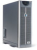
Figure 1-7. Removing the Front Bezel lock thumbscrew bezel 3 Label all hard drives and remove them from the system. NOTE: Although it is not necessary for the conversion, you might want to remove the two power-supply and cooling modules at the back of the system chassis to reduce the weight of the chassis while you are performing this procedure (see your system Installation and Troubleshooting Guide for instructions for removing and replacing these modules). 4 To remove the system left and right covers (see Figure 1-8): a Remove the two round covers from the top of the tower system. b Use a 3/16-inch hex-head (Allen) wrench to remove the hex-socket cap screws and flat washers from the top of the tower system. c Slide the left and right cover back, away from the chassis front to disengage, and pull the covers up, away from the base to remove. Rack Installation Guide 1-11
-
 1
1 -
2
-
3
-
4
-
5
-
6
-
7
-
8
-
9
-
 10
10 -
 11
11 -
 12
12 -
 13
13 -
 14
14 -
 15
15 -
 16
16 -
 17
17 -
 18
18 -
 19
19 -
 20
20 -
21
-
22
-
23
-
24
-
25
-
26
-
27
-
28
-
29
-
30
-
31
-
32
-
33
-
34
-
35
-
36
-
37
-
38
-
39
-
40
-
41
-
42
-
43
-
44
-
45
-
46
-
47
-
48
-
49
-
50
-
51
-
52
-
53
-
54
-
55
-
56
-
57
-
58
-
59
-
60
-
61
-
62
-
63
-
64
-
65
-
66
-
67
-
68
-
69
-
70
-
71
-
72
-
73
-
74
-
75
-
76
-
77
-
78
-
79
-
80
-
81
-
82
-
83
-
84
-
85
-
86
-
87
-
88
-
89
-
90
-
91
-
92
-
93
-
94
-
95
-
96
-
97
-
98
-
99
-
100
-
101
-
102
-
103
-
104
-
105
-
106
-
107
-
108
-
109
-
110
 |
 |
