Dell PowerVault 221S Optimizing Dell SCSI Solutions - Page 19
PV22xS Enclosure Overview
 |
View all Dell PowerVault 221S manuals
Add to My Manuals
Save this manual to your list of manuals |
Page 19 highlights
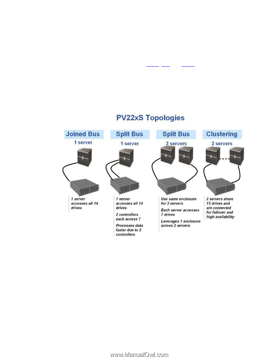
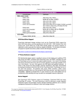
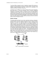
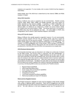
A REFERENCE GUIDE FOR OPTIMIZING DELL™ SCSI SOLUTIONS VER A02 4. PV22xS Enclosure Overview The PV22xS SCSI Enclosure provides three configuration topologies, also referred to as modes, which are end-user configurable: Joined, Split, and Cluster topologies, as shown in Figure 4-1. A 3-position switch located on the Split Bus Module (SBM) sets the desired enclosure topology. Each of these topologies will be further explained in more detail below. The configuration will not take effect until the enclosure is power cycled which is designed to protect from accidental topology changes. SCSI Enclosure Services (SES) management features are an integral part of the enclosure. SES provides a unique set of features to monitor critical environmental variables such as temperature and power status. Figure 4-1 PV22xS Topologies Joined Bus Topology This is the simplest topology of operation providing access to all 14 hard drives on one shared SCSI bus. Only one cable must be attached between the server and the primary Enclosure Management Module (EMM) in the enclosure. If operating with two EMM modules, which provide redundant SES services, a second cable should not be attached to the secondary EMM. There can only be one physical path from the enclosure to the server. Attaching a second cable is not supported and may lead to SCSI bus address contention. If SES redundancy is not required, a Terminator module can be substituted in place of secondary EMM. PAGE 19 11/17/2005
-
 1
1 -
2
-
3
-
4
-
5
-
6
-
7
-
8
-
9
-
10
-
11
-
12
-
13
-
 14
14 -
 15
15 -
 16
16 -
 17
17 -
 18
18 -
 19
19 -
 20
20 -
 21
21 -
 22
22 -
 23
23 -
 24
24 -
25
-
26
-
27
-
28
-
29
-
30
-
31
-
32
-
33
-
34
-
35
-
36
-
37
-
38
-
39
-
40
-
41
-
42
-
43
-
44
 |
 |