Dell PowerVault 221S Optimizing Dell SCSI Solutions - Page 21
Split Bus Cabling Options to a Single Host System, a Same Adapter, b Different, Adapters - disk array
 |
View all Dell PowerVault 221S manuals
Add to My Manuals
Save this manual to your list of manuals |
Page 21 highlights
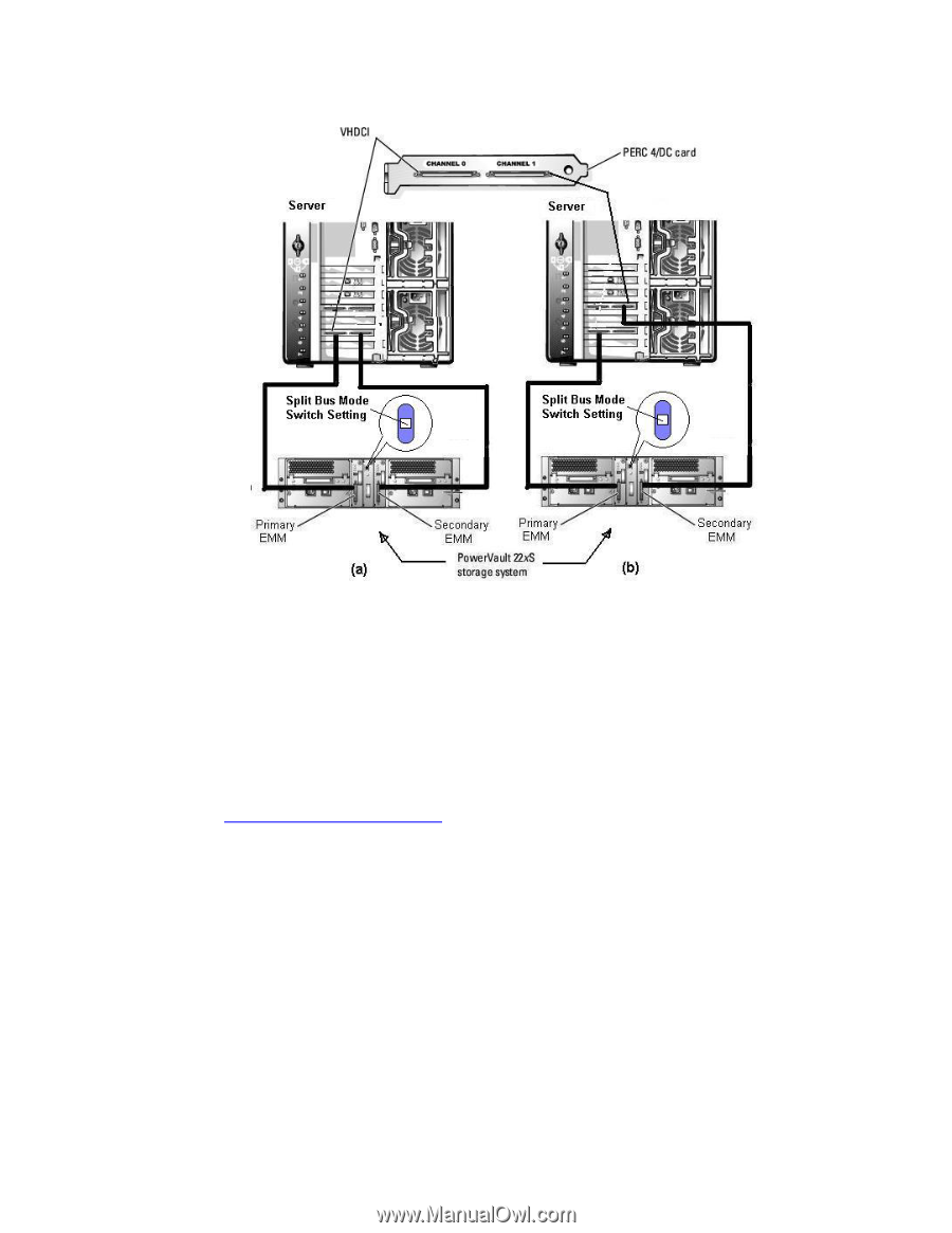
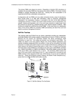
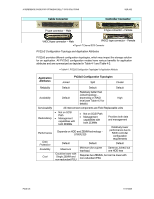
A REFERENCE GUIDE FOR OPTIMIZING DELL™ SCSI SOLUTIONS VER A02 Figure 4-3 Split Bus Cabling Options to a Single Host System, (a) Same Adapter, (b) Different Adapters Cluster Topology Cluster Topology is very similar to Joined bus topology. It provides the capability to have a single shared SCSI bus with the additional capability of allowing concurrent access from two host controllers (Figure 4-4). In this topology, only 13 HDD are available since the PERC controller on the second host system uses up one of the available SCSI addresses (refer to Figure 4-5 for more details on the specific SCSI ID reassignments). Dell™ High Availability Clustering (for more information refer to Appendix - A: References) provides the capability of configuring the PV22xS Enclosure to attach simultaneously to two different host systems. The hardware configuration of both host systems, including the SCSI RAID controller, must be identical. This is ideal for High Availability scenarios where access to the same data from two different systems is desirable. Clustering falls into two categories: Active/Active and Active/Passive. Microsoft® Cluster Service MSCS and all PowerEdge™ Clusters support both active/active and active/passive cluster configurations. The term active/active refers to a cluster with at least one virtual server running on each node. For example, in a 2-node cluster configuration, when an application is running on Node 1, Node 2 does not need to remain idle waiting for Node 1 to fail. Node 2 can run its own cluster-aware applications (or another instance of the same application) while providing failover capabilities for resources on Node 1. Node 1 in turn can provide failover capabilities for resources on Node 2. Although both nodes have physical access to the same storage, the disk arrays are mutually exclusive and cannot be simultaneously accessed by both nodes. In the event of PAGE 21 11/17/2005
-
 1
1 -
2
-
3
-
4
-
5
-
6
-
7
-
8
-
9
-
10
-
11
-
12
-
13
-
14
-
15
-
 16
16 -
 17
17 -
 18
18 -
 19
19 -
 20
20 -
 21
21 -
 22
22 -
 23
23 -
 24
24 -
 25
25 -
 26
26 -
27
-
28
-
29
-
30
-
31
-
32
-
33
-
34
-
35
-
36
-
37
-
38
-
39
-
40
-
41
-
42
-
43
-
44
 |
 |