Dell PowerVault 221S Optimizing Dell SCSI Solutions - Page 20
Split Bus Cabling to Two Host System
 |
View all Dell PowerVault 221S manuals
Add to My Manuals
Save this manual to your list of manuals |
Page 20 highlights
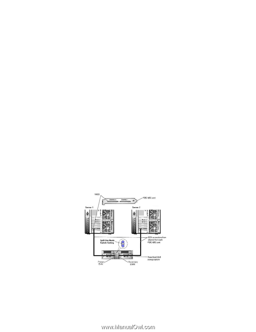
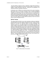
A REFERENCE GUIDE FOR OPTIMIZING DELL™ SCSI SOLUTIONS VER A02 The primary EMM must always be present. Regardless of whether SES redundancy is available, the secondary EMM slot must always have either a EMM or Terminator module installed to properly terminate the SCSI bus. Leaving this slot unpopulated is not supported and will have undesirable consequences. Configurations with two EMMs and one cable connected provide a level of redundancy. Even though there is no data path redundancy, there is enclosure management redundancy. The redundancy, however, is provided in the form of the SES enclosure management services to monitor and control critical functions such as temperature, fan speeds, initiating warnings/alerts, and in the worst case scenarios to safely power down the enclosure to prevent any potential damage under adverse thermal conditions. SES functions by default are performed by primary EMM. In the event there is a catastrophic failure of the primary EMM, the secondary EMM automatically will detect this event and perform enclosure management functions. Split Bus Topology This topology splits the PV22xS into two halves, essentially providing two independent, electrically isolated, SCSI busses capable of supporting up to seven (7) HDD on each bus. Because the two busses are electrically isolated, this allows simultaneous SCSI transactions on each bus. Two cables are required, one connected to each EMM. The cables can attach to two host systems (Figure 4-2) running different applications and operate completely independent from one another, or they can be connected to two SCSI channels on a single host system (Figure 4-3) to increase performance by splitting the I/O traffic between two different physical data paths In either case, it is highly recommended that both halves of the PV22xS be connected to the same type of SCSI RAID controllers (e.g. PERC4 and PERC4 or PERC3 and PERC3). The primary EMM monitors the state of the seven HDD in slots labeled 0 thru 5, and 8. The secondary EMM monitors the state of the seven HDD in slots labeled 9 thru 15. SES management is provided by both EMM modules to their respective SCSI hosts. SCSI failures on one bus will not affect the other bus. Power and enclosure cooling, however, are shared. Power disruptions (e.g., power short on a HDD) will affect both busses equally. Figure 4-2 Split Bus Cabling to Two Host System PAGE 20 11/17/2005
-
 1
1 -
2
-
3
-
4
-
5
-
6
-
7
-
8
-
9
-
10
-
11
-
12
-
13
-
14
-
 15
15 -
 16
16 -
 17
17 -
 18
18 -
 19
19 -
 20
20 -
 21
21 -
 22
22 -
 23
23 -
 24
24 -
 25
25 -
26
-
27
-
28
-
29
-
30
-
31
-
32
-
33
-
34
-
35
-
36
-
37
-
38
-
39
-
40
-
41
-
42
-
43
-
44
 |
 |