Dewalt DW715 Instruction Manual - Page 7
Familiarization, Bench Mounting - saw
 |
View all Dewalt DW715 manuals
Add to My Manuals
Save this manual to your list of manuals |
Page 7 highlights
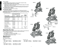
English DRIVE 120 Volt Motor 1600 Watts (max in) 4000 RPM Roller Bearings Automatic Electric Brake Familiarization Your miter saw is fully assembled in the carton. Open the box and lift the saw out by the convenient carrying handle, as shown in Figure 1. 15 Amp Motor Cut Helical Gears Carbide Blade FIG. 1 OPERATING HANDLE GUARD Place the saw on a smooth, flat surface such as a workbench or strong table. Examine Figure 2 to become familiar with the saw and its various parts. The section on adjustments will refer to these terms and you must know what and where the parts are. Press down lightly on the operating handle and pull out the lock down pin, as shown in Figure 2. Gently release the downward pressure and hold the arm allowing it to rise to its full height. Use the lock down pin when carrying the saw from one place to another. Always use the carrying handle to transport the saw or the hand indentations shown in Figure 2. Bench Mounting Holes are provided in all four feet to facilitate bench mounting, as shown in Figure 2. (Two different sized holes are provided to accommodate different sizes of screws. Use either hole, it is not necessary to use both.) Always mount your saw firmly to a stable surface to prevent movement. To enhance the tool's portability, it can be mounted to a piece of 1/2" or thicker plywood which can then be clamped to your work support or moved to other job sites and reclamped. NOTE: If you elect to mount your saw to a piece of plywood, make sure that the mounting screws don't protrude from the bottom of the wood. The plywood must sit flush on the work support. When clamping the saw to any work surface, clamp only on the clamping bosses where the mounting screw holes are located. Clamping at any other point will surely interfere with the proper operation of the saw. CAUTION: To prevent binding and inaccuracy, be sure the mounting surface is not warped or otherwise uneven. If the saw rocks on the surface place a thin piece of material under one saw foot until the saw sits firmly on the mounting surface. FIG. 2 MOTOR END CAP TRIGGER SWITCH CARRY HANDLE OPERATING HANDLE LOCK DOWN PIN BENCH MOUNTING HOLES MITER SCALE MOTOR HOUSING BEVEL SCALE LOCK DOWN PIN DUST SPOUT MITER LOCK LEVER BENCH MOUNTING HOLES BEVEL LOCK KNOB 0˚/45˚ BEVEL OVERRIDE LEVERS BEVEL STOP 33.85˚ PAWL 0˚ BEVEL STOP ADJUSTMENT SCREW 5 LEFT SIDE FENCE FENCE LOCK KNOB HAND INDENTATIONS BLADE WRENCH
-
 1
1 -
 2
2 -
 3
3 -
 4
4 -
 5
5 -
 6
6 -
 7
7 -
 8
8 -
 9
9 -
 10
10 -
 11
11 -
 12
12 -
13
-
14
-
15
-
16
-
17
-
18
-
19
-
20
-
21
-
22
-
23
-
24
-
25
-
26
-
27
-
28
-
29
-
30
-
31
-
32
-
33
-
34
-
35
-
36
-
37
-
38
-
39
-
40
-
41
-
42
-
43
-
44
-
45
-
46
-
47
-
48
-
49
-
50
-
51
-
52
 |
 |
