Dewalt DW715 Instruction Manual - Page 8
to contact the spinning saw blade - clamp
 |
View all Dewalt DW715 manuals
Add to My Manuals
Save this manual to your list of manuals |
Page 8 highlights
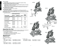
English IMPORTANT SAFETY INSTRUCTIONS Changing or Installing a New Saw Blade (Fig. 3) CAUTION: • Never depress the spindle lock button while the blade is under power or coasting. • Do not cut ferrous metal (containing iron or steel) or masonry or fiber cement product with this miter saw. FIG. 3 A 4. Depress the spindle lock button (C) while carefully rotating the saw blade by hand until the lock engages. 5. Keeping the button depressed, use the other hand and the wrench provided (D) to loosen the blade screw. (Turn clockwise, left-hand threads) 6. Remove the blade screw (E), outer clamp washer (F), and blade (G). The 1" (25.4mm) blade adapter (H), if used, and the inner clamp washer (I), may be left on the spindle. FIG. 3B EF G • Failure to do so may allow the guard to contact the spinning saw blade resulting in damage to the saw and severe personal injury. Transporting the Saw TURN OFF AND UNPLUG THE MITER SAW BEFORE ATTEMPTING TO MOVE IT OR MAKE ANY ADJUSTMENTS WHAT SO EVER! In order to conveniently carry the miter saw from place to place, a carrying handle has been included on the top of the saw arm and hand indentations in the base, as shown in Figures 2, 4. FIG. 4 H B D I Removing the Blade 1. Unplug the saw. 2. Raise the arm to the upper position and raise the lower guard (A) as far as possible. 3. Loosen, but do not remove guard bracket screw (B) until the bracket can be raised far enough to access the blade screw. Lower guard will remain raised due to the position of the guard bracket screw. FIG. 3A C NOTE: For blades with a blade hole of 5/8" (15.88mm), the 1" (25.4mm) blade adapter is not used. Installing a Blade 1. Unplug the saw. 2. With the arm raised, the lower guard held open and the pivot plate raised, place the blade on the spindle, onto the blade adapter [if using a blade with a 1" (25.4mm) diameter blade hole] and against the inner clamp washer with the teeth at the bottom of the blade pointing toward the back of the saw. 3. Assemble the outer clamp washer onto the spindle. 4. Install the blade screw and, engaging the spindle lock, tighten the screw firmly with wrench provided. (Turn counterclockwise, left-hand threads) NOTE: When using blades with a 5/8" (15.88mm) diameter blade hole, the blade adapter will not be used and should be stored in a safe place for future use. 5. Return the guard bracket to its original position and firmly tighten the guard bracket screw to hold bracket in place. WARNING: • The guard bracket must be returned to its original position and the screw tightened before activating the saw. Adjustments PERFORM ALL ADJUSTMENTS WITH THE MITER SAW UNPLUGGED. NOTE: Your miter saw is fully and accurately adjusted at the factory at the time of manufacture. If readjustment due to shipping and handling or any other reason is required, follow the steps below to adjust your saw. Once made, these adjustments should remain accurate. Take a little time now to follow these directions carefully to maintain the accuracy of which your saw is capable. MITER SCALE ADJUSTMENT (FIG. 5) Place a square against the saw's fence and blade. (Do not touch the tips of the blade teeth with the square. To do so will cause an inaccurate measurement.) Unlock miter lock lever (J) and swing the miter arm until the miter latch locks it at the 0 miter position. Do not lock miter lock lever (J). If the saw blade is not exactly perpendicular to the fence, loosen the three screws that hold the miter scale to the base and move the scale left or right until the blade is per- 6
-
 1
1 -
2
-
 3
3 -
 4
4 -
 5
5 -
 6
6 -
 7
7 -
 8
8 -
 9
9 -
 10
10 -
 11
11 -
 12
12 -
 13
13 -
14
-
15
-
16
-
17
-
18
-
19
-
20
-
21
-
22
-
23
-
24
-
25
-
26
-
27
-
28
-
29
-
30
-
31
-
32
-
33
-
34
-
35
-
36
-
37
-
38
-
39
-
40
-
41
-
42
-
43
-
44
-
45
-
46
-
47
-
48
-
49
-
50
-
51
-
52
 |
 |
