Electrolux E30DF74TPS Installation Instructions English - Page 16
Install Burner Assemblies
 |
View all Electrolux E30DF74TPS manuals
Add to My Manuals
Save this manual to your list of manuals |
Page 16 highlights
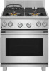
30" & 36" DUAL FUEL RANGE INSTALLATION INSTRUCTIONS 9 Install Burner Assemblies To prevent flare-ups use the cooktop with all burner caps properly installed. 9.1 Standard Sealed Burners Place a burner cap on each burner head, matching the cap size to the head size. The cap for each burner has an inner locating ring which centers the cap correctly on the burner head. Make sure each burner cap is properly aligned and level. Burners may not light or burn evenly if the burner caps are not correctly place on the head. Burner cap Locating ring Burner head Figure 27: Burner cap assembly Correct cap placement Incorrect cap placement Figure 28: Burner cap placement 9.2 Specialty Burners Install the specialty burners as shown in Figure 29. When the burner ring is properly seated, it will click into place. When the burner cap is properly set in place it should not move out of the recessed area of the burner head. To ignite properly, burner ring alignment tab must be fitted into the burner base alignment tab slot. Make sure burner cap and ring are secure before attempting to light the burner. Burner cap Burner ring alignment tab Burner alignment tab slot Figure 29: Specialty burner assembly 16 Burner ring Burner base Simmer head
-
 1
1 -
2
-
3
-
4
-
5
-
6
-
7
-
8
-
9
-
10
-
 11
11 -
 12
12 -
 13
13 -
 14
14 -
 15
15 -
 16
16 -
 17
17 -
 18
18 -
 19
19 -
 20
20 -
 21
21 -
22
-
23
-
24
-
25
-
26
-
27
-
28
-
29
-
30
-
31
-
32
-
33
-
34
-
35
-
36
-
37
-
38
-
39
-
40
-
41
-
42
-
43
-
44
-
45
-
46
-
47
-
48
-
49
-
50
-
51
-
52
-
53
-
54
-
55
-
56
 |
 |
