Epson BrightLink 585Wi Installation Guide
Epson BrightLink 585Wi Manual
 |
View all Epson BrightLink 585Wi manuals
Add to My Manuals
Save this manual to your list of manuals |
Epson BrightLink 585Wi manual content summary:
- Epson BrightLink 585Wi | Installation Guide - Page 1
Installation Guide Guide d'installation - Epson BrightLink 585Wi | Installation Guide - Page 2
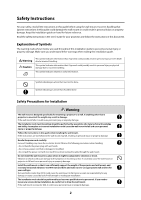
mount or could result in personal injury or property damage. Keep this installation guide on hand for future reference. Read the safety instructions in the User's Guide for your projector and follow the instructions in this document. Explanation of Symbols The warning marks shown below are used - Epson BrightLink 585Wi | Installation Guide - Page 3
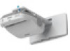
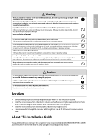
could interfere with the remote control of the projector. • Install the projector away from direct sunlight Installation Guide This guide describes how to mount the ultra-short-throw projectors BrightLink 575Wi/585Wi/575Wi+/585Wi+ and PowerLite 570/575W/580/585W to a wall using the included Epson - Epson BrightLink 585Wi | Installation Guide - Page 4
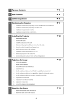
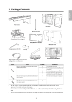
for projecting on a pre-installed wall-mounted board 2. Installation worksheet for projecting on a plain wall 3. Installation measurements in inches 4. Installation measurements in millimeters s9 5 Installing the Projector 1. Disassemble the parts 2. Assemble the parts 3. Install the wall plate on - Epson BrightLink 585Wi | Installation Guide - Page 5
installation For slide plate/projector installation For slide plate/3-axis adjustment unit installation (secured when shipped) For wall mount/wall plate installation bolts or screws supplied with the wall mount to install it as directed in this guide. Do not substitute these bolts with any other - Epson BrightLink 585Wi | Installation Guide - Page 6
. (273 mm) Adjustment from 3-axis adjustment unit installation position: 3.4 in. (87 mm) Fine adjustments the included M4 x 12 mm bolts (x6) to attach the separate pieces together before mounting the projector. See page 24 for instructions. 3.1 in. (79 mm) 6.3 in. (160 mm) 8.4 in. (213 mm) 8.7 in - Epson BrightLink 585Wi | Installation Guide - Page 7
slide adjustment range 10.7 in. (273 mm) Adjustment from 3-axis adjustment unit installation position By changing the installation position of the 3-axis adjustment unit to the front or back, you can adjust the installation position of the projector. When the screen size is less than 75 inches - Epson BrightLink 585Wi | Installation Guide - Page 8
location where the wall mount is to be installed. Make sure you also have all necessary cables for devices, such as a document camera or microphone, that you will connect to the projector. For details, refer to the online User's Guide. Connection Example External speakers Audio cable (not included - Epson BrightLink 585Wi | Installation Guide - Page 9
the Projector BrightLink 575Wi/585Wi/575Wi+/585Wi+ and PowerLite 575W/585W can project up to 100 inches diagonally for a WXGA image or 88 inches diagonally for an XGA image. PowerLite 570/580 can project up to 93 inches diagonally for an XGA image. You can project onto a pre-installed whiteboard - Epson BrightLink 585Wi | Installation Guide - Page 10
mark, then align the center line on the template sheet with the center of the image area. Follow the instructions on page 23 to install the projector. Installation worksheet for projecting on a plain wall 1. Measure the ceiling height (distance from the floor to the ceiling). _____ 2. Determine - Epson BrightLink 585Wi | Installation Guide - Page 11
the center line on the template sheet with the center of the image area. Follow the instructions on page 23 to install the projector. The tables on the following pages provide installation information for all supported image sizes. The minimum ceiling height is based on an image 30 inches from the - Epson BrightLink 585Wi | Installation Guide - Page 12
slider measure (b) are the same as the projection distance (a) when the diagonal image size (S) is 75 inches or more. Because the installation position of the projector changes when (S) is less than 75 inches, the numbers for (a) and (b) differ. 2.8 in. (70.5 mm) 8.6 in. (218 mm) Offset value for - Epson BrightLink 585Wi | Installation Guide - Page 13
arm The measurements may differ depending on the location where you place the projector. When projecting in Tele, the quality of the projected images may decrease. When using BrightLink 575Wi/585Wi/575Wi+/585Wi+ or PowerLite 575W/585W to project images at a 4:3 aspect ratio, the images are resized - Epson BrightLink 585Wi | Installation Guide - Page 14
Installation Measurements in Inches for BrightLink 575Wi/585Wi/575Wi+/585Wi+ and PowerLite 575W/585W 14 Diagonal image size (S) Min. ceiling height* Image width (w) 16:10 WXGA 4:3 XGA Image height (h) Min. Slider projection scale distance (a) mark (b) Distance from top of - Epson BrightLink 585Wi | Installation Guide - Page 15
15 Diagonal image size (S) Min. ceiling height* Image width (w) 16:10 WXGA Image height (h) Min. Slider Distance projection scale from top of distance (a) mark image to (b) wall plate (c) Min. ceiling height* Image width (w) 4:3 XGA Image height (h) Min. projection distance (a) Slider - Epson BrightLink 585Wi | Installation Guide - Page 16
Installation Measurements in Inches for PowerLite 570/580 16 Diagonal image size (S) Min. ceiling height* Image width (w) 4:3 XGA 16:10 WXGA Image height (h) Min. projection distance (a) - Epson BrightLink 585Wi | Installation Guide - Page 17
Diagonal image size (S) Min. ceiling height* Image width (w) 4:3 XGA 16:10 WXGA Image height (h) Min. Slider Distance projection scale from top of distance (a) mark image to (b) wall plate (c) Min. ceiling height* Image width (w) Image height (h) Min. Slider projection scale distance (a) - Epson BrightLink 585Wi | Installation Guide - Page 18
Installation Measurements in Millimeters for BrightLink 575Wi/585Wi/575Wi+/585Wi+ and PowerLite 575W/585W 18 Diagonal image size (S) Min. ceiling height* Image width (w) 16:10 WXGA Image height (h) Min. projection distance (a) Slider scale mark (b) Distance from top of image - Epson BrightLink 585Wi | Installation Guide - Page 19
19 Diagonal image size (S) Min. ceiling height* Image width (w) 16:10 WXGA Image height (h) Min. projection distance (a) Slider scale mark (b) Distance from top of image to wall plate (c) Min. ceiling height* Image width (w) 4:3 XGA Image height (h) Min. projection distance (a) Slider - Epson BrightLink 585Wi | Installation Guide - Page 20
Installation Measurements in Millimeters for PowerLite 570/580 20 Diagonal image size (S) Min. ceiling height* Image width (w) 4:3 XGA Image height (h) Min. projection distance (a) Slider scale mark (b) - Epson BrightLink 585Wi | Installation Guide - Page 21
Diagonal image size (S) Min. ceiling height* Image width (w) 4:3 XGA Image Min. height projection (h) distance (a) Slider scale mark (b) Distance from top of image to wall plate (c) Min. ceiling height* Image width (w) 16:10 WXGA Image height (h) Min. projection distance (a) Slider - Epson BrightLink 585Wi | Installation Guide - Page 22
interactive whiteboard, refer to the table below to identify common models and sizes. If your board is listed here, use the dimensions to reference the installation requirements found on pages 14 to 21. Diagonal size 57 inches 60 inches 63 inches 64 inches 66 inches 71 inches 75 inches 77 inches - Epson BrightLink 585Wi | Installation Guide - Page 23
cable over the wall mount. ❏ Install the wall mount so that it can sufficiently support the weight of the projector and wall mount, and resist any to fall. ❏ Epson accepts no responsibility for any damage or injury caused by lack of wall strength or inadequate installation. A Disassemble the - Epson BrightLink 585Wi | Installation Guide - Page 24
head cap bolts (x6) supplied. Washer Spring washer M4 x 12 mm hexagon socket head cap bolts 2. Attach the slide plate to the projector. Attach the slide plate to the projector using the M4 x 12 mm hexagon socket head cap bolts (x4) supplied. Slide plate M4 x 12 mm hexagon socket head cap bolts - Epson BrightLink 585Wi | Installation Guide - Page 25
or more stamp • Tighten the M4 x 12 mm hexagon socket head cap bolts (x4) supplied to install the 3-axis adjustment unit. M4 x 12 mm hexagon socket head cap bolts Spring washer Washer Bolt installation positions When the diagonal image is less than 75 inches When the diagonal image is 75 inches - Epson BrightLink 585Wi | Installation Guide - Page 26
C Install the wall plate on the wall 1. Determine the template sheet position. • From the of template sheet Center line of projection surface 2. Attach the template sheet to the wall. If you need to install a junction box, you can use the cutout areas in the wall plate for the box. The junction box - Epson BrightLink 585Wi | Installation Guide - Page 27
three places, drill the holes indicated by C in the illustration below. Four mounting holes Three mounting holes Steps 4 to 8 below provide instructions for attaching the wall plate to a concrete wall. 4. Drill holes of the following diameters and depths. Drill diameter Pilot hole depth Anchor - Epson BrightLink 585Wi | Installation Guide - Page 28
8. Tighten the nut with a wrench to secure the wall plate to the wall. D Determine the projection distance and pull out the slider 1. Using the tables on pages 14 to 21, check the number for the slider measure (b). 2. Loosen the M4 x 12 mm hexagon socket head cap bolts (x2), and then pull out the - Epson BrightLink 585Wi | Installation Guide - Page 29
English F Attach the mount arm to the wall plate 1. Insert the hexagonal shaft into the wall mount ( ). 2. Insert and turn the hexagonal shaft at the top of the mount arm into the slot on the wall plate ( ). 3. Insert and turn the M8 hexagon bolt at the bottom of the mount arm into the wall plate ( - Epson BrightLink 585Wi | Installation Guide - Page 30
4. Secure the mount arm to the wall plate by tightening the supplied M6 x 20 mm cross recessed head shoulder screws (x3) with the No.3 cross-head screwdriver ( ). M6 x 20 mm cross recessed head shoulder screws (x3) 5. Loosely tighten the M6 x 20 mm hexagon shoulder bolt supplied ( ). M6 x 20 mm - Epson BrightLink 585Wi | Installation Guide - Page 31
English G Adjust the vertical slide position of the arm 1. Adjust the vertical slide with the M8 hexagon bolt at the bottom of the wall mount, or the hexagonal shaft at the top of the wall mount. ( ). Start by aligning the notch on the arm with the stamp on the wall plate as shown below. - Epson BrightLink 585Wi | Installation Guide - Page 32
Tighten the M4 x 12 mm hexagon socket head cap bolts (x2) ( ). Slide plate Projector interface side Bolt positions Washer Spring washer M4 x 12 mm hexagon socket head cap bolts Alignment marks Warning When installing or adjusting the wall mount, do not use adhesives to prevent the screws from - Epson BrightLink 585Wi | Installation Guide - Page 33
cables such as the power cord, computer cable, HDMI cable, and USB cable to the projector. Power cord Computer cable USB cable If you are planning to run the cables inside the the cables from obstructing the image. An optional cable management system is available from Epson (part # ELPCK01). 33 - Epson BrightLink 585Wi | Installation Guide - Page 34
reduction in image quality. When using the BrightLink 575Wi/585Wi/575Wi+/585Wi+ and PowerLite 570/575W/580/585W, follow these guidelines for setting up the projector: • Make sure the image is evenly rectangular, without distortion. • Make sure the projector is tilted no more than ±3° vertically and - Epson BrightLink 585Wi | Installation Guide - Page 35
according to the signal for the connected equipment. Remote Control Aspect Ratio Normal Alternatively, set the aspect ratio are elongated horizontally to fit. BrightLink 575Wi/585Wi/575Wi+/585Wi+ and PowerLite 575W/585W • Auto: Automatically sets the aspect Projector User's Guide: Signal Menu 35 - Epson BrightLink 585Wi | Installation Guide - Page 36
1. Slide the air filter cover switch ( ) to open the air filter cover ( ). 2. Use the focus lever to adjust the focus ( ). Focus lever Air filter cover 3. After you finish making the adjustment, close the air filter cover. E Use the adjustment knob on the left side to adjust - Epson BrightLink 585Wi | Installation Guide - Page 37
English F Use the adjustment knob on the right side to adjust the horizontal rotation 1. Loosen the screws (x2) to unlock the adjustment knob( ). Screws (x2) 2. Turn the dark blue knob ( ) to adjust the horizontal rotation ( ). E J 3. After you finish making all of the adjustments in steps to , - Epson BrightLink 585Wi | Installation Guide - Page 38
E J 3. After you finish making all of the adjustments in steps to , tighten the screw you loosened in . H Adjust the horizontal slide 1. Loosen the M4 x 12 mm hexagon socket head cap bolts (x2), and then adjust the slider for the slide plate. M4 x 12 mm hexagon socket head cap bolts (x2) E J 2. - Epson BrightLink 585Wi | Installation Guide - Page 39
loosened in the first step ( ). K Turn off the display of the test pattern Press the [Esc] button on the remote control or control panel to turn off the test pattern. Warning Tighten all screws firmly. Otherwise, the projector or wall mount may fall and cause personal injury or property damage. 39 - Epson BrightLink 585Wi | Installation Guide - Page 40
A Attach the wall plate cover and end cap If you need to use a security cable, make sure you attach it before installing the wall plate cover. See page 42 for instructions. You can use the included wall plate cover extender to increase the depth of the wall plate cover and accomodate larger - Epson BrightLink 585Wi | Installation Guide - Page 41
including for maintenance and repairs. Refer to the projector User's Guide for instructions on maintenance and repairs. Warning ❏ Never loosen the bolts and nuts after installation. If you find any loose screws, tighten them firmly. Otherwise, the projector or wall mount may fall and cause personal - Epson BrightLink 585Wi | Installation Guide - Page 42
OS X users also need to install a driver that enables the pen to work. Both software programs are included with the BrightLink projector. For details, see the online User's Guide or visit: U.S.: epson.com/support/brightlinkdownloads Canada: epson.ca/support/brightlinkdownloads Latin America: global - Epson BrightLink 585Wi | Installation Guide - Page 43
de montage et provoquer des blessures corporelles ou des dommages matériels. Suivez les instructions du présent guide pour installer le support de montage. En cas de non-respect des instructions, le support de montage peut tomber et provoquer des blessures corporelles ou des dommages matériels - Epson BrightLink 585Wi | Installation Guide - Page 44
écrous et des boulons de taille inférieure à M10, le support de montage risque de tomber. Epson n'accepte aucune responsabilité pour tout dommage ou toute blessure dus à une solidité du mur insuffisante ou une installation inappropriée. L'installation doit être exécutée par au moins deux techniciens - Epson BrightLink 585Wi | Installation Guide - Page 45
) afin de réduire l'effet de parasites. À propos de ce guide d'installation Le présent guide décrit comment installer les projecteurs à ultra courte distance de projection BrightLink 575Wi/585Wi/575Wi+/585Wi+ et PowerLite 570/575W/580/585W sur un mur à l'aide du support de montage Epson inclus. 45 - Epson BrightLink 585Wi | Installation Guide - Page 46
en pouces 4. Mesures d'installation en millimètres 5 Installation du projecteur 1. Désassemblez les pièces 2. Assemblez les pièces 3. Installez la plaque murale sur le mur 4. Déterminez la distance de projection et retirez la glissière 5. Faire passer les câbles dans le bras du support de montage - Epson BrightLink 585Wi | Installation Guide - Page 47
à empreinte cruciforme 3 M6 x 20 mm avec rondelle plastique • Utilisez les vis ou les boulons fournis avec le support de montage pour installer ce dernier, comme décrit dans le présent guide. Ne leur substituez pas un autre type de boulons. • Vous devez aussi utiliser des pattes de fixation M10 - Epson BrightLink 585Wi | Installation Guide - Page 48
verticale Information supplémentaire Page de référence Support de montage : 3,0 kg (6,6 lb) po) Réglage à partir de la position d'installation du dispositif de réglage à 3 axes : le montage du projecteur. Consultez la page 68 pour obtenir les instructions. 79 mm (3,1po) 160 mm (6,3 po) 213 mm - Epson BrightLink 585Wi | Installation Guide - Page 49
vers l'avant/l'arrière Plage de réglage du coulissement du bras 273 mm (10,7 po) Réglage à partir de la position d'installation du dispositif de réglage à 3 axes En déplaçant la position d'installation du dispositif de réglage à 3 axes vers l'avant ou l'arrière, vous pouvez régler la position - Epson BrightLink 585Wi | Installation Guide - Page 50
Pour voir le poinçon, vous devez retirer les deux vis placées dans le haut et ensuite, faire glisser la rallonge du bras. Poinçon Poinçon 87 mm (3,4 po) 50 - Epson BrightLink 585Wi | Installation Guide - Page 51
èces à l'emplacement d'installation du support de montage. Assurez-vous Epson DC-06) Ordinateur Câble USB (pour la fonction Easy Interactive pour les modèles BrightLink seulement) Câble USB dédié (fourni avec la caméra de documents) Pour la fonction interactive (BrightLink 575Wi/585Wi/575Wi+/585Wi - Epson BrightLink 585Wi | Installation Guide - Page 52
du projecteur Les projecteurs BrightLink 575Wi/585Wi/575Wi+/585Wi+ et PowerLite 575W/585W peuvent projeter jusqu'à 100 po ( XGA. Vous pouvez projeter sur un tableau blanc préinstallé ou directement sur un mur ordinaire. C'est la hauteur du support mural qui détermine la taille d'image maximum et la - Epson BrightLink 585Wi | Installation Guide - Page 53
s'agira probablement de XGA (4:3). Il vous faudra peutêtre consulter le service des TI pour obtenir cette information. ___ 4:3 XGA ___ 16:10 le bas de la plaque murale (c). 9. Déterminez la position pour l'installation de votre projecteur en additionnant les _____ (f) valeurs (f), (h) et (c), - Epson BrightLink 585Wi | Installation Guide - Page 54
Suivez les directives de la page 67 pour installer le projecteur. Feuille de travail d'installation pour la projection sur un mur ordinaire 1. il s'agira probablement de XGA (4:3). Il vous faudra peut-être consulter votre service des TI pour obtenir cette information. ___ 4:3 XGA ___ 16:10 WXGA - Epson BrightLink 585Wi | Installation Guide - Page 55
centrale du gabarit avec le centre de la zone d'image. Suivez les directives de la page 67 pour installer le projecteur. Les tableaux des pages suivantes fournissent des renseignements d'installation pour toutes les tailles d'image prises en charge. La hauteur de plafond minimum est basée sur une - Epson BrightLink 585Wi | Installation Guide - Page 56
que ceux de la distance de projection (a) lorsque la taille de l'image diagonale (S) est de 75 po (190,5 cm) ou plus. Parce que la position d'installation du projecteur change lorsque (S) est moins de 75 po (190,5 cm), les chiffres pour (a) et (b) sont différents. 70,5 mm (2,8 po) 218 mm (8,6 po - Epson BrightLink 585Wi | Installation Guide - Page 57
dessous. Alignez l'encoche sur la plaque d'installation avec la position du poinçon sur la plaque murale on sur la plaque Encoche sur le bras du support Les mesures peuvent varier selon l'emplacement choisi pour le projecteur BrightLink 575Wi/585Wi/575Wi+/585Wi+ ou PowerLite 575W/ 585W est utilisé pour - Epson BrightLink 585Wi | Installation Guide - Page 58
Mesures d'installation en pouces pour BrightLink 575Wi/585Wi/575Wi+/585Wi+ et PowerLite 575W/585W 58 Taille de l'image diagonale (S) 16:10 WXGA Hauteur Largeur Hauteur Dist. de du de de proj. plafond l'image l'image min. (a) min.* (l) (h) Repères de - Epson BrightLink 585Wi | Installation Guide - Page 59
59 Taille de l'image diagonale (S) Hauteur du plafond min.* 16:10 WXGA Largeur Hauteur Dist. de de de proj. l'image l'image min. (a) (l) (h) Repères de glissière (b) Dist. du haut de l'image à la plaque murale (c) Hauteur du plafond min.* Largeur de l'image (l) 4:3 XGA Hauteur Dist. - Epson BrightLink 585Wi | Installation Guide - Page 60
Mesures d'installation en pouces pour les projecteurs PowerLite 570/580 60 Taille de 4:3 XGA l'image Hauteur Largeur Hauteur Dist. de diagonale (S) du plafond de l'image de l'image - Epson BrightLink 585Wi | Installation Guide - Page 61
Taille de 4:3 XGA l'image Hauteur Largeur Hauteur Dist. de diagonale du de de proj. (S) plafond l'image l'image min. (a) min.* (l) (h) Repères de glissière (b) Dist. du haut de l'image à la plaque murale (c) Hauteur du plafond min.* Largeur de l'image (l) 16:10 WXGA Hauteur Dist. de - Epson BrightLink 585Wi | Installation Guide - Page 62
Mesures d'installation en millimètres pour BrightLink 575Wi/585Wi/575Wi+/585Wi+ et PowerLite 575W/585W 62 Taille de l'image diag. (S) Haut. du plafond min.* Larg. de l'image (l) 16:10 WXGA Haut. de Dist. de l'image proj. (h) min. (a) Repères de - Epson BrightLink 585Wi | Installation Guide - Page 63
63 Taille de l'image diag. (S) Haut. du plafond min.* Larg. de l'image (l) 16:10 WXGA Haut. de Dist. de l'image proj. (h) min. (a) Repères de glissière (b) 4:3 XGA Dist. du haut de l'image à la plaque murale (c) Haut. du plafond min.* Larg. de l'image (l) Haut. de l'image (h) Dist. de - Epson BrightLink 585Wi | Installation Guide - Page 64
Mesures d'installation en millimètres pour les projecteurs PowerLite 570/580 64 Taille de l'image diag. (S) Haut. du plafond min.* 4:3 XGA Larg. de l'image (l) Haut. de l'image (h) - Epson BrightLink 585Wi | Installation Guide - Page 65
65 Taille de l'image diag. (S) 4:3 XGA Haut. du plafond min.* Larg. de l'image (l) Haut. de l'image (h) Dist. de proj. min. (a) Repères de glissière (b) Dist. du haut de l'image à la plaque murale (c) 16:10 WXGA Haut. du plafond min.* Larg. de l'image (l) Haut. de l'image (h) Dist. de - Epson BrightLink 585Wi | Installation Guide - Page 66
pour identifier les modèles et tailles communes. Si votre tableau est listé ici, utilisez les dimensions pour vous référer aux exigences d'installation des pages 58 à 65. Tailles des tableaux blancs interactifs Taille diagonale 16:10 WXGA 4:3 XGA 16:9 grand écran 57 po - PolyVision TS410 - Epson BrightLink 585Wi | Installation Guide - Page 67
support de montage et le projecteur. Ce support de montage doit être installé sur un mur en béton. Vérifiez donc le poids du projecteur et du support de montage avant l'installation taille inférieure à M10, le support de montage risque de tomber. ❏ Epson n'accepte aucune responsabilité pour tout - Epson BrightLink 585Wi | Installation Guide - Page 68
tête cylindrique à six pans M4 x 12 mm Rondelle élastique Rondelle 3. Fixez le dispositif de réglage à 3 axes au support de montage. • Choisissez la position selon laquelle vous souhaitez installer le dispositif de réglage à 3 axes. Installez-le au niveau du poinçon lorsque l'image est inférieure - Epson BrightLink 585Wi | Installation Guide - Page 69
les boulons à tête cylindrique à six pans M4 x 12 mm (x4) fournis pour installer le dispositif de réglage à 3 axes. Boulons à tête cylindrique à six pans M4 x 12 mm Rondelle élastique Rondelle Positions d'installation des boulons Lorsque l'image diagonale est inférieure à 75 po (190,5 cm) Lorsque - Epson BrightLink 585Wi | Installation Guide - Page 70
,5 mm (2,8 po) Ligne de la fiche modèle Ligne centrale de la surface de projection 2. Fixez la fiche modèle au mur. Si vous devez installer une boîte de jonction, vous pouvez utiliser les zones de découpe de la plaque murale pour la boîte. La boîte de jonction - Epson BrightLink 585Wi | Installation Guide - Page 71
, percez les trous indiqués par C sur l'illustration ci-dessous. Quatre trous de montage Trois trous de montage Les étapes 4 à 8 ci-dessous fournissent les instructions pour fixer la plaque murale à un mur de béton. 4. Percez des trous des diamètres et des profondeurs suivants. Diamètre de per - Epson BrightLink 585Wi | Installation Guide - Page 72
de la glissière (b). 2. Desserrez les boulons à tête cylindrique à six pans M4 x 12 mm (x2), puis retirez la glissière sur le support de montage. Alignez la glissière avec la mesure (b+x) équivalente à la mesure de la glissière (b) additionnée à l'épaisseur de l'écran de projection (x). Boulons - Epson BrightLink 585Wi | Installation Guide - Page 73
passer les câbles dans le bras du support de montage F Fixez le bras du support de montage à la plaque murale 1. Insérez l'arbre hexagonal dans le support de montage ( ). 2. Insérez et faites tourner l'arbre hexagonal sur la partie supérieure du bras du support de montage dans le logement de la - Epson BrightLink 585Wi | Installation Guide - Page 74
la plaque murale ( ). Mise en garde Veillez à ne pas bloquer les câbles entre le bras du support de montage et la plaque murale. Arbre hexagonal Boulon à six pans M8 4. Fixez le bras du support de montage à la plaque murale en serrant les vis à épaulement à tête à empreinte cruciforme M6 x 20 mm - Epson BrightLink 585Wi | Installation Guide - Page 75
Français 5. Desserrez légèrement le boulon à épaulement à six pans M6 x 20 mm ( ). Boulon à épaulement à six pans M6 x 20 mm Rondelle élastique Rondelle 75 - Epson BrightLink 585Wi | Installation Guide - Page 76
du bras 1. Réglez le coulissement vertical à l'aide du boulon à six pans M8 sur la partie inférieure du support de montage, ou de l'arbre hexagonal sur la partie supérieure de la plaque d'installation. ( ). Commencez par aligner l'encoche sur le bras avec le poinçon sur la plaque murale tel qu - Epson BrightLink 585Wi | Installation Guide - Page 77
x 12 mm Marques d'alignement Avertissement Lorsque vous installez ou ajustez le support de montage, n'utilisez pas d'adhésifs afin d'éviter que les vis ne se desserrent et n'utilisez pas d'huiles ou lubrifiants pour la plaque d'installation du projecteur. Le boîtier risque de se détériorer et le - Epson BrightLink 585Wi | Installation Guide - Page 78
système de gestion des câbles afin d'éviter que les câbles obstruent l'image. Un système de gestion des câbles est disponible en option chez Epson (numéro de pièce : ELPCK01). 78 - Epson BrightLink 585Wi | Installation Guide - Page 79
Corner du projecteur. Vous risqueriez de détériorer la qualité de l'image. Lorsque vous utilisez les projecteurs BrightLink 575Wi/585Wi/575Wi+/585Wi+ et PowerLite 570/575W/580/ 585W, suivez ces directives pour configurer le projecteur : • Assurez-vous que l'image est uniformément rectangulaire, sans - Epson BrightLink 585Wi | Installation Guide - Page 80
sont étirées horizontalement pour tenir à l'écran. BrightLink 575Wi/585Wi/575Wi+/585Wi+ et PowerLite 575W/585W • Automatique : Règle automatiquement le rapport hauteur/largeur et le param les images peuvent être rognées, selon la résolution. s Guide de l'utilisateur du projecteur : Menu Signal 80 - Epson BrightLink 585Wi | Installation Guide - Page 81
Français D Réglez la mise au point 1. Faites glisser le levier du capot du filtre à air ( ) pour ouvrir le capot du filtre à air ( ). 2. Utilisez le levier de mise au point pour régler la mise au point ( ). Levier de mise au point Capot du filtre à air 3. Une fois le réglage terminé, fermez le - Epson BrightLink 585Wi | Installation Guide - Page 82
E J 3. Une fois tous les réglages des étapes à terminés, serrez la vis que vous avez desserrée à l'étape . F Utilisez la poignée de réglage sur le côté droit pour régler le roulis horizontal 1. Desserrez les vis (x2) pour déverrouiller la poignée de réglage ( ). Vis (x2) 2. Tournez la poignée bleu - Epson BrightLink 585Wi | Installation Guide - Page 83
Français G Utilisez la poignée de réglage dans le haut pour régler l'inclinaison verticale 1. Desserrez la vis ( ) pour déverrouiller la poignée de réglage. Vis 2. Tournez la poignée bleu pâle ( ) pour régler l'inclinaison verticale ( ). E J 3. Une fois tous les réglages des étapes à terminés, - Epson BrightLink 585Wi | Installation Guide - Page 84
glez le coulissement vers l'avant/l'arrière 1. Desserrez les boulons à tête cylindrique à six pans M4 x 12 mm (x2), puis réglez la glissière du support de montage. Boulons à tête cylindrique à six pans M4 x 12 mm (x2) E J 2. Une fois tous les réglages des étapes à terminés, serrez les boulons à tête - Epson BrightLink 585Wi | Installation Guide - Page 85
Appuyez sur le bouton [Esc] de la télécommande ou du panneau de commande pour supprimer la mire. Avertissement Serrez fermement toutes les vis. Sinon, le support de montage ou le projecteur pourrait tomber et provoquer des blessures corporelles ou des dommages matériels. 85 - Epson BrightLink 585Wi | Installation Guide - Page 86
Fixation des caches A Fixez le cache du support de montage et le capuchon de protection Si vous devez utiliser un câble de sécurité, assurez-vous de le fixer avant d'installer le cache de la plaque murale. Consultez la page 88 pour obtenir les instructions. Vous pouvez utiliser la rallonge du capot - Epson BrightLink 585Wi | Installation Guide - Page 87
-vous au Guide de l'utilisateur de votre projecteur pour plus d'informations sur l'entretien et les réparations. Avertissement ❏ Ne desserrez jamais les écrous et les boulons après l'installation. Si vous constatez le moindre jeu, resserrez fermement les vis concernées. Sinon, le support de montage - Epson BrightLink 585Wi | Installation Guide - Page 88
. Pour obtenir plus de détails, consultez le Guide de l'utilisateur en ligne ou sur l'un des sites Web suivants : É.-U. : epson.com/support/brightlinkdownloads Canada : epson.ca/support/brightlinkdownloads Fixation d'un câble de sécurité Si le projecteur doit être installé dans une pièce qui ne sera
-
 1
1 -
 2
2 -
 3
3 -
 4
4 -
 5
5 -
 6
6 -
 7
7 -
8
-
9
-
10
-
11
-
12
-
13
-
14
-
15
-
16
-
17
-
18
-
19
-
20
-
21
-
22
-
23
-
24
-
25
-
26
-
27
-
28
-
29
-
30
-
31
-
32
-
33
-
34
-
35
-
36
-
37
-
38
-
39
-
40
-
41
-
42
-
43
-
44
-
45
-
46
-
47
-
48
-
49
-
50
-
51
-
52
-
53
-
54
-
55
-
56
-
57
-
58
-
59
-
60
-
61
-
62
-
63
-
64
-
65
-
66
-
67
-
68
-
69
-
70
-
71
-
72
-
73
-
74
-
75
-
76
-
77
-
78
-
79
-
80
-
81
-
82
-
83
-
84
-
85
-
86
-
87
-
88
 |
 |
Installation Guide
Guide d’installation