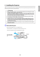
Epson BrightLink 585Wi Installation Guide - Page 26
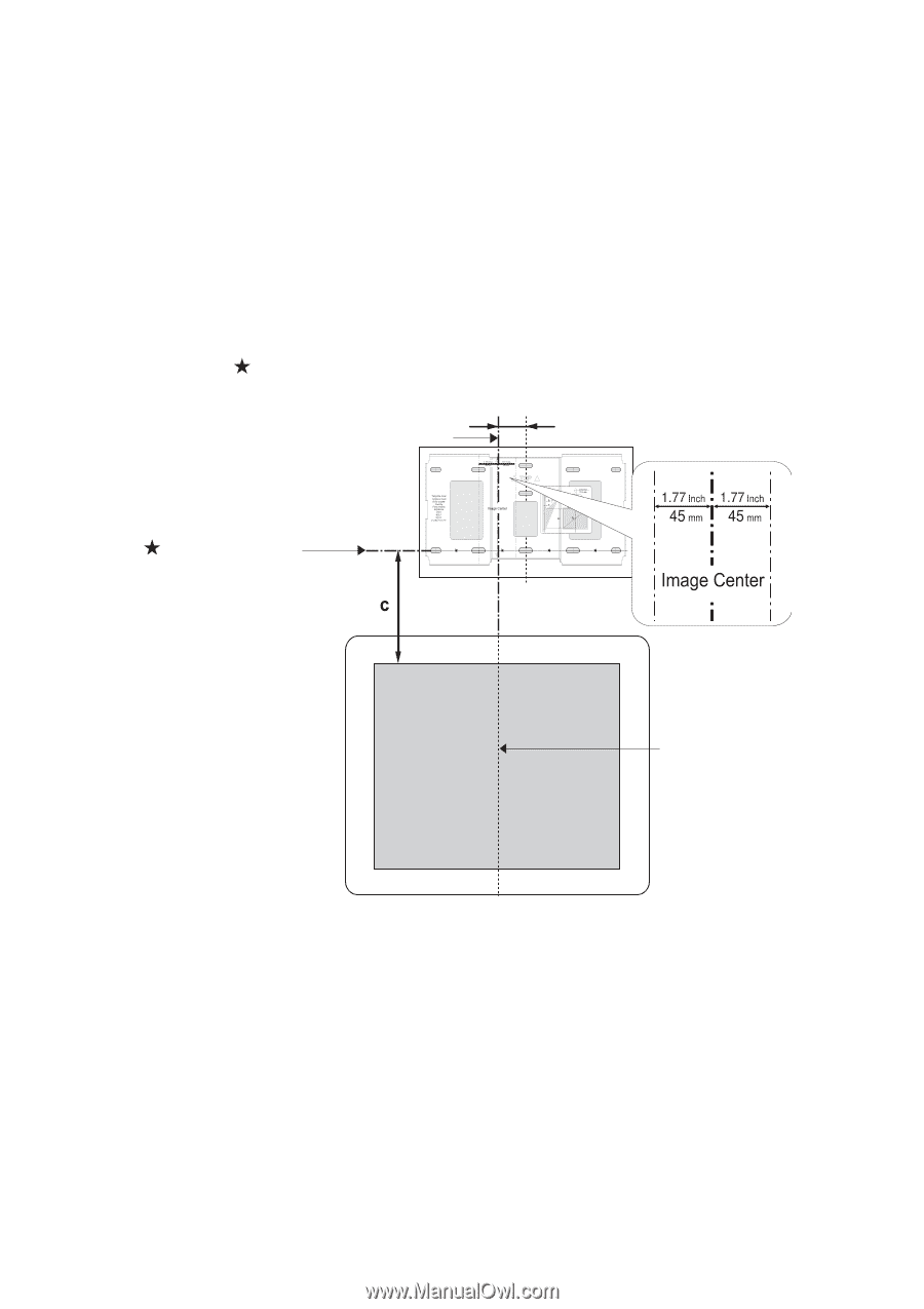
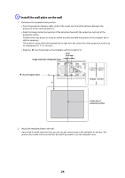
Install the wall plate on the wall, to a maximum of 1.77 in. 45 mm.
 |
View all Epson BrightLink 585Wi manuals
Add to My Manuals
Save this manual to your list of manuals |
Page 26 highlights
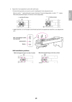
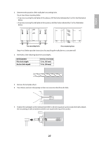
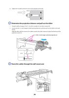
C Install the wall plate on the wall 1. Determine the template sheet position. • From the projection distance table, confirm the screen size (S) and the distance between the projection surface and wall plate (c). • Align the Image Center line (vertical) of the template sheet with the center line (vertical) of the projection surface. Confirm where the beams or studs are within the wall, and shift the position of the template left or right as necessary. The position can be shifted horizontally left or right from the center line of the projection surface up to a maximum of 1.77 in. (45 mm.) • Align the line (horizontal) on the template with the height of (c). 2.8 in. (70.5 mm) Image Center line of template sheet line of template sheet Center line of projection surface 2. Attach the template sheet to the wall. If you need to install a junction box, you can use the cutout areas in the wall plate for the box. The junction box needs to be recessed into the wall if you want to use the wall plate cover. 26
-
 1
1 -
2
-
3
-
4
-
5
-
6
-
7
-
8
-
9
-
10
-
11
-
12
-
13
-
14
-
15
-
16
-
17
-
18
-
19
-
20
-
 21
21 -
 22
22 -
 23
23 -
 24
24 -
 25
25 -
 26
26 -
 27
27 -
 28
28 -
 29
29 -
 30
30 -
 31
31 -
32
-
33
-
34
-
35
-
36
-
37
-
38
-
39
-
40
-
41
-
42
-
43
-
44
-
45
-
46
-
47
-
48
-
49
-
50
-
51
-
52
-
53
-
54
-
55
-
56
-
57
-
58
-
59
-
60
-
61
-
62
-
63
-
64
-
65
-
66
-
67
-
68
-
69
-
70
-
71
-
72
-
73
-
74
-
75
-
76
-
77
-
78
-
79
-
80
-
81
-
82
-
83
-
84
-
85
-
86
-
87
-
88
 |
 |