Epson BrightLink 695Wi Installation Guide - Control Pad and Touch Unit - Page 15
Install the Touch Unit Bracket
 |
View all Epson BrightLink 695Wi manuals
Add to My Manuals
Save this manual to your list of manuals |
Page 15 highlights
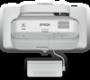
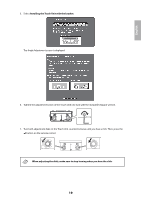
E Install the Touch Unit Bracket 1. Secure the installation plate on the wall using three (3) M4 wood screws or anchor bolts (not included). 2. Attach the Touch Unit to the securing plate with the M4 × 25 mm hexagon socket head cap bolts (×2) supplied. Adjust the position of the Touch Unit so that the two screw holes align with the holes on the securing plate. Tighten the bolts with the supplied hexagon wrench. Caution When attaching the Touch Unit to the securing plate, be careful not to trap your fingers or any other part of your body between the magnets and the securing plate. 14
-
 1
1 -
2
-
3
-
4
-
5
-
6
-
7
-
8
-
9
-
 10
10 -
 11
11 -
 12
12 -
 13
13 -
 14
14 -
 15
15 -
 16
16 -
 17
17 -
 18
18 -
 19
19 -
 20
20 -
21
-
22
-
23
-
24
-
25
-
26
-
27
-
28
-
29
-
30
-
31
-
32
-
33
-
34
-
35
-
36
-
37
-
38
-
39
-
40
-
41
-
42
-
43
-
44
-
45
-
46
-
47
-
48
-
49
-
50
-
51
-
52
-
53
-
54
-
55
-
56
-
57
-
58
-
59
-
60
-
61
-
62
-
63
-
64
-
65
-
66
-
67
-
68
-
69
-
70
-
71
-
72
-
73
-
74
-
75
-
76
-
77
-
78
-
79
-
80
-
81
-
82
-
83
-
84
-
85
-
86
-
87
-
88
-
89
-
90
 |
 |

14
E
Install the Touch Unit Bracket
1.
Secure the installation plate on the wall using three (3) M4 wood screws or anchor bolts (not included).
2.
Attach the Touch Unit to the securing plate with the M4 × 25 mm hexagon socket head cap bolts (×2)
supplied.
Adjust the position of the Touch Unit so that the two screw holes align with the holes on the securing
plate. Tighten the bolts with the supplied hexagon wrench.
When attaching the Touch Unit to the securing plate, be careful not to trap your fingers or any
other part of your body between the magnets and the securing plate.
Caution