Epson BrightLink 695Wi Installation Guide - Control Pad and Touch Unit - Page 31
Install the Touch Unit
 |
View all Epson BrightLink 695Wi manuals
Add to My Manuals
Save this manual to your list of manuals |
Page 31 highlights
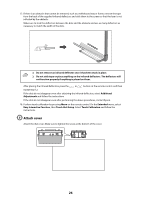
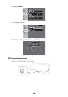
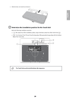
E Install the Touch Unit • For magnetic boards, place the back of the Touch Unit on the screen surface to secure it. Caution When installing the Touch Unit on a magnetic surface, be careful not to trap your fingers or any other part of your body between the magnets and the installation surface. • For non-magnetic boards or screens, attach the spacers to the screw holes on the back of the Touch Unit Secure the Touch Unit with three (3) M4 screws (not included). 0.8 in. (20 mm) 1.7 in. (43 mm) 30
-
 1
1 -
2
-
3
-
4
-
5
-
6
-
7
-
8
-
9
-
10
-
11
-
12
-
13
-
14
-
15
-
16
-
17
-
18
-
19
-
20
-
21
-
22
-
23
-
24
-
25
-
 26
26 -
 27
27 -
 28
28 -
 29
29 -
 30
30 -
 31
31 -
 32
32 -
 33
33 -
 34
34 -
 35
35 -
 36
36 -
37
-
38
-
39
-
40
-
41
-
42
-
43
-
44
-
45
-
46
-
47
-
48
-
49
-
50
-
51
-
52
-
53
-
54
-
55
-
56
-
57
-
58
-
59
-
60
-
61
-
62
-
63
-
64
-
65
-
66
-
67
-
68
-
69
-
70
-
71
-
72
-
73
-
74
-
75
-
76
-
77
-
78
-
79
-
80
-
81
-
82
-
83
-
84
-
85
-
86
-
87
-
88
-
89
-
90
 |
 |

30
E
Install the Touch Unit
•
For magnetic boards, place the back of the Touch Unit on the screen surface to secure it.
•
For non-magnetic boards or screens, attach the spacers to the screw holes on the back of the Touch
Unit
Secure the Touch Unit with three (3) M4 screws (not included).
When installing the Touch Unit on a magnetic surface, be careful not to trap your fingers or any
other part of your body between the magnets and the installation surface.
Caution
1.7 in. (43 mm)
0.8 in. (20 mm)