Epson BrightLink 695Wi Installation Guide - Control Pad and Touch Unit - Page 16
If the distance from the wall to the surface of the whiteboard is greater than 2
 |
View all Epson BrightLink 695Wi manuals
Add to My Manuals
Save this manual to your list of manuals |
Page 16 highlights
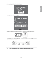
English 3. Attach the Touch Unit and securing plate to the installation plate with the M4 × 12 mm hexagon socket head cap bolts (×2) supplied. Tighten the bolts to the securing plate with the supplied hexagon wrench. 4. Measure the distance from the wall to the surface of the whiteboard (f ). ❏ If the distance from the wall to the surface of the whiteboard is greater than 2 inches (51 mm), you must install the Touch Unit on the whiteboard. ❏ If the frame of the whiteboard extends more than 0.1 inch (3 mm) away from the board surface, you must install the Touch Unit on the whiteboard. 15
-
 1
1 -
2
-
3
-
4
-
5
-
6
-
7
-
8
-
9
-
10
-
 11
11 -
 12
12 -
 13
13 -
 14
14 -
 15
15 -
 16
16 -
 17
17 -
 18
18 -
 19
19 -
 20
20 -
 21
21 -
22
-
23
-
24
-
25
-
26
-
27
-
28
-
29
-
30
-
31
-
32
-
33
-
34
-
35
-
36
-
37
-
38
-
39
-
40
-
41
-
42
-
43
-
44
-
45
-
46
-
47
-
48
-
49
-
50
-
51
-
52
-
53
-
54
-
55
-
56
-
57
-
58
-
59
-
60
-
61
-
62
-
63
-
64
-
65
-
66
-
67
-
68
-
69
-
70
-
71
-
72
-
73
-
74
-
75
-
76
-
77
-
78
-
79
-
80
-
81
-
82
-
83
-
84
-
85
-
86
-
87
-
88
-
89
-
90
 |
 |

15
English
3.
Attach the Touch Unit and securing plate to the installation plate with the M4 × 12 mm hexagon socket
head cap bolts (×2) supplied.
Tighten the bolts to the securing plate with the supplied hexagon wrench.
4.
Measure the distance from the wall to the surface of the whiteboard (f).
❏
If the distance from the wall to the surface of the whiteboard is greater than 2
inches (51 mm), you must install the Touch Unit on the whiteboard.
❏
If the frame of the whiteboard extends more than 0.1 inch (3 mm) away from the
board surface, you must install the Touch Unit on the whiteboard.