Fujitsu 4340C Operator's Guide - Page 109
Index
 |
UPC - 097564304156
View all Fujitsu 4340C manuals
Add to My Manuals
Save this manual to your list of manuals |
Page 109 highlights
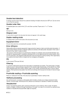
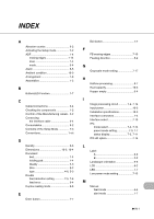
INDEX A Abrasion counter 6-2 Activating the Setup mode 7-2 ADF 1-4 erasing edges 7-14 lever 1-4 mode 6-4 Alarm 6-5 Ambient condition 10-3 Arrangement 1-6 Assemblies 1-5 B Button/LED Function 1-7 C Cable Connections 2-4 Checking the components 1-2 Confirm of the Manufacturing Labels .. 2-2 Connecting the interface cable 2-4 Consumables 9-2 Contents of the Setup Mode 7-3 Conventions 1-viii D Density 9-6 Dimensions 10-3, 10-4 Document bed 1-4 holding pad 1-4 Quality 5-3 Size 5-2 type 4-6, 5-3 Double feed detection setting 7-5, 7-6 feed error 6-4 Duplex reading mode 9-5 E Enter button 1-7 Exit button 1-7 F FB erasing edges 7-16 Feeding direction 5-2 G Grayscale mode setting 7-17 H Halfone processing 9-7 Heat capacity 10-3 Hopper empty 6-4 I Image processing circuit 7-4, 7-14 Input power 10-3 Installation specifications 10-3 Interface connectors 1-4 Interface select 7-13 IPC mode select 7-4, 7-14 preset mode setting 7-3, 7-7 status display 7-3, 7-11 IPC-4D option 7-14 L Label A 2-2 B 2-2 Landscape orientation 9-6 LCD 6-2 LED 1-7 Low power mode setting 7-12 M Manual feed mode 4-4 start mode 1-7 G IN-1
-
 1
1 -
2
-
3
-
4
-
5
-
6
-
7
-
8
-
9
-
10
-
11
-
12
-
13
-
14
-
15
-
16
-
17
-
18
-
19
-
20
-
21
-
22
-
23
-
24
-
25
-
26
-
27
-
28
-
29
-
30
-
31
-
32
-
33
-
34
-
35
-
36
-
37
-
38
-
39
-
40
-
41
-
42
-
43
-
44
-
45
-
46
-
47
-
48
-
49
-
50
-
51
-
52
-
53
-
54
-
55
-
56
-
57
-
58
-
59
-
60
-
61
-
62
-
63
-
64
-
65
-
66
-
67
-
68
-
69
-
70
-
71
-
72
-
73
-
74
-
75
-
76
-
77
-
78
-
79
-
80
-
81
-
82
-
83
-
84
-
85
-
86
-
87
-
88
-
89
-
90
-
91
-
92
-
93
-
94
-
95
-
96
-
97
-
98
-
99
-
100
-
101
-
102
-
103
-
 104
104 -
 105
105 -
 106
106 -
 107
107 -
 108
108 -
 109
109 -
 110
110 -
 111
111 -
 112
112 -
 113
113 -
 114
114
 |
 |