Fujitsu 4340C Operator's Guide - Page 23
Units and Assemblies, Units - pad assembly
 |
UPC - 097564304156
View all Fujitsu 4340C manuals
Add to My Manuals
Save this manual to your list of manuals |
Page 23 highlights
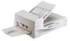
Units and Assemblies This section shows the exterior view and assemblies of the scanner. This section also provides the name of each part and describes its functions. I Units (1)Document cover (4)Automatic document feeder(ADF) (3)Document holding pad (2)Document bed (5)Stacker (7)Transport Lever (6)Operator panel (9)ADF lever (8)ADF paper chute (17)Spare Pad ASSY (16)Third party slot (Option board Slot) (10)Power switch (11)Power Inlet (12)EXT connector (15)Interface connector (14)SCSI ID switch (13)SCSI terminator switch NOTICE The transport lever should be switched to the operating position when the scanner is to be used. Refer to Chapter2 "Placing the Transport Lever (page 2-3)" for details. G 1-3
-
 1
1 -
2
-
3
-
4
-
5
-
6
-
7
-
8
-
9
-
10
-
11
-
12
-
13
-
14
-
15
-
16
-
17
-
 18
18 -
 19
19 -
 20
20 -
 21
21 -
 22
22 -
 23
23 -
 24
24 -
 25
25 -
 26
26 -
 27
27 -
 28
28 -
29
-
30
-
31
-
32
-
33
-
34
-
35
-
36
-
37
-
38
-
39
-
40
-
41
-
42
-
43
-
44
-
45
-
46
-
47
-
48
-
49
-
50
-
51
-
52
-
53
-
54
-
55
-
56
-
57
-
58
-
59
-
60
-
61
-
62
-
63
-
64
-
65
-
66
-
67
-
68
-
69
-
70
-
71
-
72
-
73
-
74
-
75
-
76
-
77
-
78
-
79
-
80
-
81
-
82
-
83
-
84
-
85
-
86
-
87
-
88
-
89
-
90
-
91
-
92
-
93
-
94
-
95
-
96
-
97
-
98
-
99
-
100
-
101
-
102
-
103
-
104
-
105
-
106
-
107
-
108
-
109
-
110
-
111
-
112
-
113
-
114
 |
 |

●
1-3
This section shows the exterior view and assemblies of the scanner. This section also provides the name
of each part and describes its functions.
■
Units
NOTICE
The transport lever should be switched to the operating position when the scanner is to be used. Refer to
Chapter2 "Placing the Transport Lever (page 2-3)" for details.
Units and Assemblies