Gateway GT5436E 8511861 - Gateway Computer Hardware Reference for Windows Vist - Page 62
Remove the three screws that secure the power supply
 |
View all Gateway GT5436E manuals
Add to My Manuals
Save this manual to your list of manuals |
Page 62 highlights
CHAPTER 4: Upgrading Your Computer 7 Find the memory module banks on your system board. 8 Gently pull the plastic tabs away from the sides of the memory modules, then remove them. 9 Disconnect the power and data cables from the system board, noting their locations and orientation. (You will reconnect the cables after you install the new board.) 10 Remove the three screws that secure the power supply to your computer. Screws 11 Slide the power supply away from the back of your computer, then pull it down and remove it. 56
-
 1
1 -
2
-
3
-
4
-
5
-
6
-
7
-
8
-
9
-
10
-
11
-
12
-
13
-
14
-
15
-
16
-
17
-
18
-
19
-
20
-
21
-
22
-
23
-
24
-
25
-
26
-
27
-
28
-
29
-
30
-
31
-
32
-
33
-
34
-
35
-
36
-
37
-
38
-
39
-
40
-
41
-
42
-
43
-
44
-
45
-
46
-
47
-
48
-
49
-
50
-
51
-
52
-
53
-
54
-
55
-
56
-
 57
57 -
 58
58 -
 59
59 -
 60
60 -
 61
61 -
 62
62 -
 63
63 -
 64
64 -
 65
65 -
 66
66 -
 67
67 -
68
-
69
-
70
-
71
-
72
-
73
-
74
-
75
-
76
-
77
-
78
-
79
-
80
-
81
-
82
-
83
-
84
-
85
-
86
-
87
-
88
-
89
-
90
-
91
-
92
-
93
-
94
-
95
-
96
-
97
-
98
-
99
-
100
-
101
-
102
-
103
-
104
-
105
-
106
-
107
-
108
-
109
-
110
-
111
-
112
-
113
-
114
-
115
-
116
-
117
-
118
-
119
-
120
-
121
-
122
-
123
-
124
-
125
-
126
-
127
-
128
-
129
-
130
-
131
-
132
-
133
-
134
-
135
-
136
-
137
-
138
 |
 |

CHAPTER
4
: Upgrading Your Computer
56
7
Find the memory module banks on your system board.
8
Gently pull the plastic tabs away from the sides of the
memory modules, then remove them.
9
Disconnect the power and data cables from the system
board, noting their locations and orientation. (You will
reconnect the cables after you install the new board.)
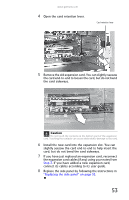
10
Remove the three screws that secure the power supply
to your computer.
11
Slide the power supply away from the back of your
computer, then pull it down and remove it.
Screws