Gateway NV-59C Service Guide
Gateway NV-59C Manual
 |
View all Gateway NV-59C manuals
Add to My Manuals
Save this manual to your list of manuals |
Gateway NV-59C manual content summary:
- Gateway NV-59C | Service Guide - Page 1
Gateway NV59C Series Service Guide Service guide files and updates are available on the ACER/CSD web; for more information, please refer to http://csd.acer.com.tw PRINTED IN TAIWAN - Gateway NV-59C | Service Guide - Page 2
Revision History Please refer to the table below for the updates made on Gateway NV59C service guides. Date Chapter Updates II - Gateway NV-59C | Service Guide - Page 3
) assumes the entire cost of all necessary servicing, repair, and any incidental or consequential damages resulting from any defect in the software. Acer is a registered trademark of Acer Corporation. Intel is a registered trademark of Intel Corporation. Other brand and product names are trademarks - Gateway NV-59C | Service Guide - Page 4
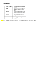
Conventions The following conventions are used in this manual: SCREEN MESSAGES NOTE WARNING CAUTION IMPORTANT Denotes actual or software problems. Reminds you to do specific actions relevant to the accomplishment of procedures. NOTE: This symbol where placed in the Service Guide designates a - Gateway NV-59C | Service Guide - Page 5
on card, modem, or extra memory capability). These LOCALIZED FEATURES will NOT be covered in this generic service guide. In such cases, part number change is made, it will not be noted in the printed Service Guide. For ACER-AUTHORIZED SERVICE PROVIDERS, your Acer office may have a DIFFERENT part - Gateway NV-59C | Service Guide - Page 6
VI - Gateway NV-59C | Service Guide - Page 7
23 Gateway NV59C BIOS 24 Information 24 Main 25 Security 26 Boot 29 Exit 30 BIOS Flash Utilities 31 DOS Flash Utility 32 WinFlash Utility 34 Remove HDD/BIOS Password Utilities 35 Machine Disassembly and Replacement 41 Disassembly Requirements 41 Pre-disassembly Instructions 42 - Gateway NV-59C | Service Guide - Page 8
Door 134 Replacing the ODD Module 135 Replacing the SD Dummy Card 136 Replacing the SIM Card 137 Replacing the Battery 138 Troubleshooting 139 Common Problems 139 Power On Issue 140 No Display Issue 141 Random Loss of BIOS Settings 142 LCD Failure 143 Built-In Keyboard Failure 143 VIII - Gateway NV-59C | Service Guide - Page 9
CMOS Jumper 163 BIOS Recovery by Crisis Disk 164 FRU (Field Replaceable Unit) List 165 EasyNote Exploded Diagrams 166 Main Assembly 166 Upper Assembly 167 LCD Assembly 168 FRU List 169 Screw List 176 Model Definition and Configuration 178 Gateway NV59C 179 Test Compatible Components - Gateway NV-59C | Service Guide - Page 10
Table of Contents X - Gateway NV-59C | Service Guide - Page 11
1066 MHz FSB, 35 W), supporting Intel® 64 architecture, Intel® Smart Cache* • Intel® Core i3-330M/i3-350M processor (3 MB L3 cache, 2.13/2.26 GHz, 1066 MHz FSB, 35 W), supporting Intel® 64 architecture, Intel® Smart Cache* • Mobile Intel® HM55 Express Chipset System Memory • Dual-channel DDR3 SDRAM - Gateway NV-59C | Service Guide - Page 12
card reader, supporting: • Secure Digital™ (SD) Card, MultiMediaCard (MMC), Memory Stick™ (MS), Memory Stick PRO™ (MS PRO), xD-Picture Card™ (xD) Audio Two built-in stereo speakers High-definition audio support Built-in microphone MS-Sound compatible Optical Media Drive • 4X Blu-ray Disc™/DVD - Gateway NV-59C | Service Guide - Page 13
keys, Windows® key, international language support I/O interface • Multi-in-1 card reader • Three USB 2.0 ports • HDMI™ port with HDCP support • External display (VGA) port • Headphone/speaker/line-out jacks • Microphone-in jack • Ethernet (RJ-45) port • DC-in jack for AC adapter Software • Gateway - Gateway NV-59C | Service Guide - Page 14
• WildTangent® Gateway Edition (except China, Japan, Hong Hong, Korea) • Windows Live™ Essentials - Wave 3.2 (Mail, Photo Gallery, Live™ Messenger, Movie Maker, Writer) Optional Items • Bluetooth® 2.1 module • 1 GB / 2 GB / 4 GB DDR3 1333 MHz soDIMM module • 4400 mAh 6-cell Li-ion battery pack - Gateway NV-59C | Service Guide - Page 15
System Block Diagram Chapter 1 5 - Gateway NV-59C | Service Guide - Page 16
(for selected models). Internal microphone for recording sound. Display screen HDD Also called Liquid-Crystal Display (LCD), displays computer output. Indicates when the hard disk drive is active. Communication indicator Indicates the computer's wireless connectivity device status. Chapter 1 - Gateway NV-59C | Service Guide - Page 17
Comfortable support area for your hands when you use the computer. 8 Click buttons (left The left and right buttons function like the left and right) and right mouse buttons. 9 Power1 Indicates the computer's power status. Battery1 Indicates the computer's battery status. 1. Charging: The - Gateway NV-59C | Service Guide - Page 18
3 4 5 67 Item DC-in jack Description Connects to an AC adapter Ventilation slots External display (VGA) port Ethernet (RJ-45) port HDMI USB 2.0 ports Microphone-in jack Ethernet 10/100-based network. Connect to HDMI devices Connect to USB 2.0 devices (e.g. USB mouse, USB camera). Accepts input - Gateway NV-59C | Service Guide - Page 19
mouse, USB camera). Internal optical drive; accepts CDs or DVDs. Lights up when the optical drive is active. Ejects the optical disk from the drive. Ejects the optical drive tray when the computer is turned the lock. Some keyless models are also available. Bottom View 1 6 2 5 3 4 Chapter 1 9 - Gateway NV-59C | Service Guide - Page 20
the computer's battery status. NOTE: 1. Charging: The light shows amber when the battery is charging. 2. Fully charged: The light shows green when in AC mode. Indicates when the hard disk drive is active. Communication indicator Indicates the computer's wireless connectivity device status - Gateway NV-59C | Service Guide - Page 21
it - and your fingers - dry and clean. The TouchPad is sensitive to finger movement; hence, the lighter the touch, the better the response. Tapping too hard will not increase the TouchPad's responsiveness. Chapter 1 11 - Gateway NV-59C | Service Guide - Page 22
full-sized keys and an embedded numeric keypad, separate cursor, lock, Windows, function and special keys. Lock Keys and embedded numeric keypad The keyboard has two lock keys which you can toggle on and off. Lock key Caps Lock Num Lock Description When Caps Lock is on, all alphabetic - Gateway NV-59C | Service Guide - Page 23
connected to a network domain), or switch users (if you're not connected to a network domain) < > + : Minimizes all windows < > + : Open the + : Open Windows Mobility Center < > + : Display the System Properties dialog box < > + : Restore minimized windows to the desktop - Gateway NV-59C | Service Guide - Page 24
+ Icon Function Communication Device On/Off Sleep Description Toggles WiFi, 3G and Bluetooth on and off using a pop-up window. Puts the computer in Sleep mode. Display toggle Display Blank Switches display output between the display screen, external monitor (if connected) and both. Turns - Gateway NV-59C | Service Guide - Page 25
Hotkey Icon Function Social Networking + + + + Page Up Page Down Home End Description Opens Facebook Login screen. Scrolls the page up. Scrolls the page down. Scrolls to the top of the page. Scrolls to the bottom of the page. Chapter 1 15 - Gateway NV-59C | Service Guide - Page 26
Power On-die Cache Front Side Bus Specification • Intel Calpella (Discrete/UMA: Arrandale with Gfx) • Intel PCH: HM55 (4MB SPI ROM) Intel 35W Acer Spec (dBA) 28 31 34 37 40 • Throttling 50%: On=100°C, Off=85°C • OS Shutdown: 104°C • BIOS H/W Shutdown: 92°C Item BIOS vendor Insyde BIOS BIOS - Gateway NV-59C | Service Guide - Page 27
Supports memory size per socket Supports DIMM type Supports DIMM Speed Supports DIMM voltage Specification • Flash ROM 4MB • Support ISIPP • Support Acer UI • Support multi-boot • Suspend to RAM (S3)/Disk (S4) • Various hot-keys for system control • Support SMBIOS 2.3, PCI2.2. • Refer to Acer BIOS - Gateway NV-59C | Service Guide - Page 28
for SNMP MIB II, Ethernet-like MIB, and Ethernet MIB (IEEE 802.3z, Clause 30) • Self-boot feature, utilizing smaller EEPROM size with ability to use on-chip memory • Supports iSCSI boott • PCI Express CLKREQ support • Integrated switching regulator for improved power consumption • IPv4 and IPv6 - Gateway NV-59C | Service Guide - Page 29
Hard Disk Drive Interface Item Vendor & Model Name Seagate Capacity (MB) 160, 250, 320, 500 Bytes per sector Data heads Drive Format Disks Spindle speed (RPM) Performance Specifications Buffer size Interface DC Power Requirements Voltage tolerance 5V ±5% Specification HGST Toshiba - Gateway NV-59C | Service Guide - Page 30
to "Orange Book Part 3": read & write) DVD Write: DVD Data & Video CD Read: CD-DA, CD-ROM Mode-1, CD-ROM/XA Mode-2 Form-1 and Mode-2 Form-2, CD-i, VideoCD, CD-Text Loading mechanism Drawer (Solenoid Open) Tact SW (Open) Emergency Release (draw open hole) Power Requirement Input Voltage DC - Gateway NV-59C | Service Guide - Page 31
Power and Keyboard Controller Item Controller Specification GP8T Type; 358.27mm x 113.44mm x 4.9mm Features • Support Windows keys and Application keys • Standard pitch, 2.5 mm travel length • Multi-Language support Hotkeys See "Hot Keys" on page 14. Battery Item Vendor & model name Battery - Gateway NV-59C | Service Guide - Page 32
Support Color Viewing Angle (up/down/right/ left) Temperature Range (°C) Operating Storage (shipping) Specification AUO/CPT/CMO/Samsung/LCD/INL 15.6 inches 1366 x 768 WXGA Clare 0.204 x 0.204 Normal 220 500 typical 8 1.25 max LVDS 262K 15/35/45/45 0 to +50 -20 to +60 Card Reader Item Part - Gateway NV-59C | Service Guide - Page 33
, you may need to run Setup. Please also refer to Chapter 4 Troubleshooting when problem arises. To activate the BIOS Utility, press F2 during POST (when "Press to enter Setup" message is prompted on the bottom of screen). The default parameter of F12 Boot Menu is set to "disabled". If you - Gateway NV-59C | Service Guide - Page 34
Intel(R) Core(TM) i3 CPU 2.13GHz M 330 @ 2.13GHz TOSHIBA MK3265GSX Y9U5A09MA TSSTcorp CDDVDW TS-L633C V1.02 ATI VGA VER012.015.000.003.036141 NEW902101400114B4A1601 Gateway NV59C Gateway by the Open Software Foundation (OSF) as part of the Distributed Computing Environment (DCE). 24 Chapter 2 - Gateway NV-59C | Service Guide - Page 35
D2D Recovery function. The function allows the user to create a hidden partition on hard disc drive to store operation system and restore the system to factory defaults. Control the mode in which the SATA controller should operate. Control the graphics display mode. Note: Switchable Graphics is - Gateway NV-59C | Service Guide - Page 36
of the user password. Shows the setting of the hard disk password. Press Enter to set the supervisor password. When set, this password protects the BIOS Setup Utility from unauthorized access. The user can not , you may have to return your notebook computer to your dealer to reset it. 26 Chapter 2 - Gateway NV-59C | Service Guide - Page 37
password length can not exceed 8 alphanumeric characters (A-Z, a-z, 0-9, not case sensitive). Retype the password in the "Confirm New Password" field. When you are done, press F10 to save the changes and exit the BIOS Setup Utility. Removing a Password Follow these steps: 1. Use the ↑ and ↓ keys to - Gateway NV-59C | Service Guide - Page 38
Set". 5. If desired, you can enable the Password on boot parameter. 6. When you are done, press F10 to save the changes and exit the BIOS Setup Utility. If the verification is OK, the screen will display as following. Setup Notice Changes have been saved. [Continue] The password setting is complete - Gateway NV-59C | Service Guide - Page 39
boot devices to load the operating system. Bootable devices includes the USB diskette drives, the onboard hard disk drive and the DVD drive in the module bay. Select Boot Devices to select specific devices to support boot. InsydeH20 Setup Utility Information Main Security Boot Exit Rev. 3.5 Boot - Gateway NV-59C | Service Guide - Page 40
Exit The Exit screen allows you to save or discard any changes you made and quit the BIOS Utility. Information Main InsydeH20 Setup Utility Security Boot Exit Rev. 3.5 Exit Saving Changes Exit Discarding Changes Load Setup Defaults Discard Changes Save Changes Item Specific - Gateway NV-59C | Service Guide - Page 41
create a Crisis Recovery Diskette before you use the Flash utility. NOTE: Do not install memory-related drivers (XMS, EMS, DPMI) when you use the Flash. NOTE: Please use the AC adaptor power supply when you run the Flash utility. If the battery pack does not contain enough power to finish BIOS - Gateway NV-59C | Service Guide - Page 42
Utility Perform the following steps to use the DOS Flash Utility: 1. Press F2 during boot to enter the Setup Menu. 2. Select Boot Menu to modify the boot priority order, for example, if using USB HDD to Update BIOS, move USB HDD to position 1. InsydeH20 Setup Utility Information Main Security Boot - Gateway NV-59C | Service Guide - Page 43
4. In flash BIOS, the message Please do not remove AC Power Source displays. NOTE: If the AC power is not connected, the following message displays. Plug in the AC power to continue. 5. Flash is complete when the message Flash programming complete displays. Chapter 2 33 - Gateway NV-59C | Service Guide - Page 44
WinFlash Utility Perform the following steps to use the WinFlash Utility: 1. Double-click the WinFlash executable. 2. Click OK to begin the update. A progress screen displays. 34 Chapter 2 - Gateway NV-59C | Service Guide - Page 45
Password Utilities This section provides you with details about removing HDD/BIOS password: Remove HDD Password: If you key in the wrong HDD password three times, an error is generated. To reset the HDD password, perform the following steps: 1. After the error is displayed, select the Enter Unlock - Gateway NV-59C | Service Guide - Page 46
Removing BIOS Passwords To clear the User or Supervisor passwords, open the DIMM door and use a metal instrument to short the RTC_RST point. Cleaning BIOS Passwords To clean the User or Supervisor passwords, perform the following steps: 1. From a DOS prompt, execute clnpwd.exe 2. Press 1 or 2 to - Gateway NV-59C | Service Guide - Page 47
Using Boot Sequence Selector The Boot Sequence Selector allows the boot order to be changed without accessing the BIOS. To use Boot Sequence Selector, perform the following steps: 1. Enter into DOS. 2. Execute BS.exe to display the usage screen. 3. Select the desired boot sequence - Gateway NV-59C | Service Guide - Page 48
EEPROM Input: dmitools /wp Acer Write Serial Number to EEPROM Input: dmitools /ws 01234567890123456789 4 ). Write UUID to EEPROM (Create UUID from Intel WFM20.pdf) Input: dmitools /wu 5). Write Asset Tag to EEPROM Input: dmitools /wa Acet Asstag NOTE: When using any of the Write options, restart the - Gateway NV-59C | Service Guide - Page 49
Using the LAN MAC EEPROM Utility You can use the MAC.BAT utility to write the MAC.CFG file to the EEPROM under DOS mode. 1. Use a text editor (for example: Notepad) to open the MAC.CFG file. You can see the MAC.CFG contents as below: WriteData = '001122334455' StartAddr=7A WriteLeng=6 KeepByte=0 - Gateway NV-59C | Service Guide - Page 50
40 Chapter 2 - Gateway NV-59C | Service Guide - Page 51
3 Machine Disassembly and Replacement IMPORTANT: The outside housing and color may vary from the mass produced model. This chapter contains step-by-step procedures on how to disassemble the notebook computer for maintenance and troubleshooting. Disassembly Requirements To disassemble the computer - Gateway NV-59C | Service Guide - Page 52
Instructions Before proceeding with the disassembly procedure, make sure that you do the following: 1. Turn off the power to the system and all peripherals. 2. Unplug the AC adapter and all power and signal cables from the system. 3. Place the system on a flat, stable surface. 4. Remove the battery - Gateway NV-59C | Service Guide - Page 53
cannot be disassembled outside of factory conditions. If any part of the LCD Module is faulty, such as the camera, antenna or LCD panel, the whole module must be replaced. The disassembly process is divided into the following stages: • External module disassembly • Main unit disassembly • LCD - Gateway NV-59C | Service Guide - Page 54
and instructs you on the components that need to be removed during servicing. For example, if you want to remove the keyboard, you must first remove the switch board. Turn off system and peripherals power Disconnect power and signal cables from system Remove Battery Remove SD Dummy Card Remove - Gateway NV-59C | Service Guide - Page 55
Removing the Battery Pack 1. Turn computer over. Slide the battery lock in the direction shown. 2. Slide and hold the battery release latch to the release position (1), then lift out the battery pack from the main unit (2). 2 1 NOTE: The battery has been highlighted with a yellow oval as shown in - Gateway NV-59C | Service Guide - Page 56
Removing the SIM Card 1. See "Removing the Battery Pack" on page 45. 2. Push the SIM card all the way in to eject it. 3. Pull it out from the slot. 46 Chapter 3 - Gateway NV-59C | Service Guide - Page 57
Removing the SD Dummy Card 1. Push the SD dummy card all the way in to eject it. 2. Pull it out from the slot. Chapter 3 47 - Gateway NV-59C | Service Guide - Page 58
Removing the Optical Drive Module 1. See "Removing the Battery Pack" on page 45. 2. Remove the screw securing the ODD module. Step ODD Module Size M2.5*8 Quantity 1 3. Pull the optical drive module out from the chassis. Screw Type 48 Chapter 3 - Gateway NV-59C | Service Guide - Page 59
4. Remove the two (2) screws securing the ODD bracket and remove the ODD bracket from the optical disk drive module. Step ODD Bracket Size M2*3 Quantity 2 Screw Type 5. Remove the ODD bezel by prying the top edge away and clear of the module. Chapter 3 49 - Gateway NV-59C | Service Guide - Page 60
the HDD/WLAN/DIMM Door 1. Remove three (3) screws from the HDD/WLAN/DIMM door. Step HDD/WLAN/ DIMM door Size M2.5*8 Quantity 2 2. Lift the door beginning from the inner edge as - Gateway NV-59C | Service Guide - Page 61
Removing the 3G Module 1. Loosen one (1) screw on the 3G Cover. Step 3G Cover Size M2.5*8 Quantity 1 2. Lift the 3G Cover from the left edge first, then remove completely. Screw Type 3. Remove the two (2) antenna cables from the 3G module. Chapter 3 51 - Gateway NV-59C | Service Guide - Page 62
4. Remove one (1) screw from the 3G module. 5. Lift the 3G card from the slot. 52 Chapter 3 - Gateway NV-59C | Service Guide - Page 63
Removing the DIMM Module 1. See "Removing the HDD/WLAN/DIMM Door" on page 50. 2. Push out the release latches on both sides of the DIMM socket to release the DIMM module. 3. Remove the DIMM module. 4. Repeat steps 2 and 3 for the second DIMM module if present. Chapter 3 53 - Gateway NV-59C | Service Guide - Page 64
Removing the WLAN Module 1. See "Removing the HDD/WLAN/DIMM Door" on page 50. 2. Disconnect the two (2) antenna cables from the WLAN Board. 3. Move the antenna away and remove the one (1) screw to release the WLAN Board. Step WLAN Module Size M2*3 Quantity 1 Screw Type 54 Chapter 3 - Gateway NV-59C | Service Guide - Page 65
4. Detach the WLAN Board from the WLAN socket. NOTE: When reattaching the antennas, ensure the cables are tucked into the chassis to prevent damage. Chapter 3 55 - Gateway NV-59C | Service Guide - Page 66
Removing the Hard Disk Drive Module 1. See "Removing the HDD/WLAN/DIMM Door" on page 50. 2. Using the pull-tab, slide the HDD Module in the direction of the arrow to disconnect the - Gateway NV-59C | Service Guide - Page 67
4. Remove the four (4) screws (two each side) securing the hard disk to the carrier. Step HDD Carrier Size M3*3 5. Remove the HDD from the carrier. Quantity 4 Screw Type Chapter 3 57 - Gateway NV-59C | Service Guide - Page 68
Remove Keyboard Remove Upper Cover Upper Cover Lower Cover Remove Power Board Remove Left Speaker Module Remove Right Speaker Module Remove USB Board Remove TouchPad Bracket Remove USB Board Remove Card Reader Board Remove Mainboard Remove Thermal Module Remove CPU Remove Bluetooth - Gateway NV-59C | Service Guide - Page 69
Step TouchPad Bracket Mainboard Thermal Module Screw M2*3 M2.5*5 M1.98*3.0 Quantity 2 1 4 Part No. 86.WJ802.004 86.WJ802.001 86.WJ802.004 Chapter 3 59 - Gateway NV-59C | Service Guide - Page 70
Removing the Keyboard 1. Unlock the six (6) keyboard locks. 2. Pry up the centre of the Keyboard and rotate it upward away from the Upper Cover. 3. Turn the keyboard over on to the TouchPad area to expose the FPC connector. 60 Chapter 3 - Gateway NV-59C | Service Guide - Page 71
4. Open the locking latch and disconnect the FPC from the mainboard. 5. Lift the keyboard clear of the Upper Cover. Chapter 3 61 - Gateway NV-59C | Service Guide - Page 72
the Upper Cover 1. See "External Module Disassembly Process" on page 44. 2. Turn the computer over. Remove the eleven (11) screws on the lower cover and five (5) screws from the battery bay. Step Upper Cover (red callout) Size M2.5*8 Battery Bay (green callout) M2*3 Quantity 11 5 Screw - Gateway NV-59C | Service Guide - Page 73
3. Turn the computer over. Disconnect the following four (4) cables from the Mainboard. D C A B Chapter 3 63 - Gateway NV-59C | Service Guide - Page 74
cable off the adhesive as shown. cable. 6. Release the locking latch on B and remove the cable as shown. 7. Release the locking latch on C and remove the cable as shown. 8. Release the locking latch on D and remove the cable as shown. NOTE: Avoid pulling on cables directly to prevent damage to - Gateway NV-59C | Service Guide - Page 75
9. Remove the seven (7) screws on the Upper Cover as shown. Step Upper Cover Size M2.5*5 Quantity 7 Screw Type 10. Starting at the top right side of the cover, pry apart the Upper and Lower Covers as shown. Work along the front edge of the casing to the left as shown, then lift the - Gateway NV-59C | Service Guide - Page 76
the Upper Cover" on page 62. 2. Locate the Left Speaker Module on the Upper Cover as shown. 3. Remove two (2) screws from the left speaker module. Step Left Speaker Module Size M2*3 Quantity 2 Screw Type 4. Lift the Speaker clear of the Upper Cover. Ensure - Gateway NV-59C | Service Guide - Page 77
" on page 62. 2. Locate the Right Speaker Module on the Upper Cover as shown. 3. Remove the one (1) securing screw from the Right Speaker Module. Step Right Speaker Module Size M2*3 Quantity 1 Screw Type 4. Remove the Right Speaker Module cable from the cable channel. Ensure that the cable is - Gateway NV-59C | Service Guide - Page 78
5. Lift the Right Speaker Module clear of the upper cover. 68 Chapter 3 - Gateway NV-59C | Service Guide - Page 79
Upper Cover" on page 62. 2. Turn the upper cover over. Pass the cable through the upper cover as shown. 3. Remove two (2) screws from the power board. Step Power board Size M2*3 Quantity 2 Screw Type 4. Remove the power board assembly and lift the power board clear of the device. Chapter 3 69 - Gateway NV-59C | Service Guide - Page 80
the TouchPad Bracket IMPORTANT: The TouchPad Board cannot be removed individually. To replace the TouchPad Board, replace the entire Upper Cover. 1. See "Removing the Upper Cover" on page 62. 2. Lift the FFC to detach the adhesive securing the cable to the Upper Cover. 3. Release the FFC locking - Gateway NV-59C | Service Guide - Page 81
4. Remove the one (1) screw from TouchPad bracket. Step TouchPad Bracket Size M2*3 Quantity 1 5. Pry the Touchpad bracket off the adhesive and remove it as shown. Screw Type Chapter 3 71 - Gateway NV-59C | Service Guide - Page 82
Removing the Card Reader Board 1. See "Removing the Upper Cover" on page 62. 2. Unlock the mainboard to card reader cable connector. 3. Remove the cable from the chassis by pulling up on the adhesive. 4. Remove one (1) screw from the card reader board. Step Card Reader Size M2*3 Quantity 1 Screw - Gateway NV-59C | Service Guide - Page 83
5. Lift the card reader board clear of the device. Chapter 3 73 - Gateway NV-59C | Service Guide - Page 84
Removing the USB Board 1. See "Removing the Upper Cover" on page 62. 2. Unlock the mainboard to USB cable connector. 3. Remove the cable from the chassis by pulling up on the adhesive. 4. Remove one (1) screw from the USB board. Step USB Size M2*3 Quantity 1 Screw Type 74 Chapter 3 - Gateway NV-59C | Service Guide - Page 85
5. Lift the USB board clear of the device. Chapter 3 75 - Gateway NV-59C | Service Guide - Page 86
Removing the Bluetooth Board 1. See "Removing the Upper Cover" on page 62. 2. Pry the Bluetooth board from the adhesive. 3. Disconnect the mainboard to Bluetooth cable. 4. Lift the Bluetooth board away from the cable channel as shown. 76 Chapter 3 - Gateway NV-59C | Service Guide - Page 87
Removing the Mainboard 1. See "Removing the Upper Cover" on page 62. 2. Unlock the microphone cable connector and disconnect the cable. 3. Disconnect the LVDS cable. Chapter 3 77 - Gateway NV-59C | Service Guide - Page 88
from the Mainboard. Step Mainboard Size M2.5*5 Quantity 1 Screw Type 5. Lift the mainboard from the chassis, right edge first to free it from the lower case. CAUTION: Do not remove the mainboard completely. The mainboard is still connected to the chassis. 78 Chapter 3 - Gateway NV-59C | Service Guide - Page 89
6. Carefully turn the mainboard over and place it on a clean, dust-free surface. 7. Disconnect the power cable. 8. Remove the mainboard from the chassis and turn it over. NOTE: Circuit boards >10 cm² have been highlighted with a yellow rectangle as shown in the previous - Gateway NV-59C | Service Guide - Page 90
9. Remove the adhesive tape from the bluetooth cable. 10. Unlock the connector and disconnect the bluetooth to mainboard cable. 80 Chapter 3 - Gateway NV-59C | Service Guide - Page 91
the Upper Cover" on page 62. 2. See "Removing the Mainboard" on page 77. 3. Disconnect the fan cable. 4. Remove the four (4) securing screws (in reverse numerical order from screw 4 to screw 1) from the Thermal Module. 2 1 4 3 Step Thermal Module Size M1.98*3.0 Quantity 4 Screw Type - Gateway NV-59C | Service Guide - Page 92
5. Carefully lift the Thermal Module clear of the Mainboard. 82 Chapter 3 - Gateway NV-59C | Service Guide - Page 93
are damaged, the CPU may malfunction. Place the CPU on a clean, dry surface when it is not installed. 1. See "Removing the Thermal Module" on page 81. 2. Using a flat-bladed screw driver, rotate the CPU locking screw 180° clockwise as shown. 3. Lift the CPU clear of the socket as shown. Chapter - Gateway NV-59C | Service Guide - Page 94
LCD Module Disassembly Process LCD Module Disassembly Flowchart Remove LCD Assembly Remove LCD Bezel Remove Camera Module Remove Inverter Board Remove LCD Panel Remove LCD Brackets and FPC Cable Remove Antennas Remove Microphone Cable Screw List Step LCD Bezel LCD Panel LCD Brackets Inverter - Gateway NV-59C | Service Guide - Page 95
the LCD Assembly 1. See "Removing the Upper Cover" on page 62. 2. Turn the device over and pass the black and white antenna cables through the lower cover. 3. Free the black and white antenna cables from the cable channel as shown. 4. Continue removing the white antenna cable from the cable channel - Gateway NV-59C | Service Guide - Page 96
5. Remove the LVDS cable from the cable channel. 6. Remove the adhesive tape from the black antenna cable and free the cable from the cable channel. 86 Chapter 3 - Gateway NV-59C | Service Guide - Page 97
7. Remove four (4) screws from the LCD assembly. Step LCD assembly Size M2.5*8 Quantity 4 8. Remove the LCD assembly from the lower cover. Screw Type Chapter 3 87 - Gateway NV-59C | Service Guide - Page 98
the LCD Assembly" on page 85. 2. Remove the two (2) bezel screw caps and screws. Step LCD Bezel Size M2.5*6 Quantity 2 Screw Type 3. Starting from the bottom edge of the bezel, pry the bezel upwards and away from the panel. Work along the right side toward the top of the bezel, prying - Gateway NV-59C | Service Guide - Page 99
Removing the Camera Module 1. See "Removing the LCD Assembly" on page 85. 2. Locate the Camera Module at the top of the LCD Module and disconnect the camera cable. 3. Remove the Camera from the module. Chapter 3 89 - Gateway NV-59C | Service Guide - Page 100
the LCD Assembly" on page 85. 2. Remove the adhesive tape from the inverter cables. 3. Remove one (1) screw from the inverter board. Step Inverter Board Size M2.5*5 Quantity 1 Screw Type 4. Using both hands, rotate the inverter board around the hook to - Gateway NV-59C | Service Guide - Page 101
5. Turn the board over and disconnect the cable. Chapter 3 91 - Gateway NV-59C | Service Guide - Page 102
Removing the LCD Panel 1. See "Removing the Camera Module" on page 89. 2. Remove the two (2) securing screws from the LCD Panel. Step LCD Panel Size M2.5*6 Quantity 2 Screw Type 3. Remove the adhesive tape from the cable and continue removing the cable from the channel. 92 Chapter 3 - Gateway NV-59C | Service Guide - Page 103
4. Lift the LCD Panel clear of the module. Chapter 3 93 - Gateway NV-59C | Service Guide - Page 104
the LCD Brackets and FPC Cable 1. See "Removing the LCD Panel" on page 92. 2. Remove the six (6) securing screws (three on each side) from the LCD Panel brackets. Step LCD Brackets Size M2*3 Quantity 6 3. Remove the LCD brackets from the LCD Panel. Screw Type 4. Peel back the mylar securing - Gateway NV-59C | Service Guide - Page 105
5. Disconnect the LVDS cable from the panel. Chapter 3 95 - Gateway NV-59C | Service Guide - Page 106
Removing the Microphone Cable 1. See "Removing the LCD Panel" on page 92. 2. Remove the cable bundle from the hinge channel. 3. Peel back the foil tabs and remove the microphone cable from the cable channel. 4. Continue removing the cable from the cable channel. 96 Chapter 3 - Gateway NV-59C | Service Guide - Page 107
5. Lift the microphone set clear of the panel. Chapter 3 97 - Gateway NV-59C | Service Guide - Page 108
Removing the Antennas 1. See "Removing the LCD Panel" on page 92. 2. Remove the black antenna from the cable channel. 3. Peel back the foil tabs and remove the cable from the cable channel. 4. Pry the antenna assembly clear of the device. 98 Chapter 3 - Gateway NV-59C | Service Guide - Page 109
5. Remove the white antenna from the hinge channel. 6. Peel back the foil tabs and remove the cable from the cable channel. 7. Pry the antenna assembly clear of the device. Chapter 3 99 - Gateway NV-59C | Service Guide - Page 110
LCD Module Reassembly Procedure Replacing the Antennas 1. Adhere the white antenna assembly to the LCD cover. 2. Run the cable along the cable channel and fold over the foil tabs to secure the cable in place. 3. Run the white antenna along the hinge channel. 100 Chapter 3 - Gateway NV-59C | Service Guide - Page 111
4. Adhere the black antenna assembly on the LCD cover. 5. Run the cable along the cable channel and fold over the foil tabs to secure the cable in place. 6. Run the black antenna cable along the cable channel. Chapter 3 101 - Gateway NV-59C | Service Guide - Page 112
Replacing the Microphone Cable 1. Place the microphone set in the panel. 2. Fold the foil tab over to secure. 3. Fold over the along the hinge channel. IMPORTANT: Ensure that the LCD cable runs between the callouts to avoid trapping when the panel is replaced in the LCD Module. 102 Chapter 3 - Gateway NV-59C | Service Guide - Page 113
Replacing the LCD Brackets and FPC Cable 1. Connect the LVDS cable to the LCD panel. 2. Adhere the LVDS mylar to the LCD panel. 3. Attach the LCD brackets to the LCD Panel. Chapter 3 103 - Gateway NV-59C | Service Guide - Page 114
4. Replace six (6) securing screws (three on each side) of the LCD Panel brackets. 104 Chapter 3 - Gateway NV-59C | Service Guide - Page 115
Replacing the LCD Panel 1. Place the LCD Panel in the module. 2. Run the cable along the channel in the LCD Module as shown. 3. Apply the adhesive strip to hold the cable in place. 4. Secure the panel using two (2) securing screws. Chapter 3 105 - Gateway NV-59C | Service Guide - Page 116
Replacing the Inverter Board 1. Connect the cable to the underside of the inverter 2. Rotate the board around the hook as shown. board. 3. Replace one (1) screw to secure the inverter board. 4. Secure the adhesive table on the inverter cables. 106 Chapter 3 - Gateway NV-59C | Service Guide - Page 117
Replacing the Camera Module 1. Place the Camera in the module. 2. Connect the camera cable. Chapter 3 107 - Gateway NV-59C | Service Guide - Page 118
Replacing the LCD Bezel 1. Replace the bezel and press down until there are no gaps between the bezel and the LCD Module. IMPORTANT: Ensure that the LCD cables pass through the hinge wells and are not trapped by the bezel. 2. Replace the two (2) screws and screw caps. 108 Chapter 3 - Gateway NV-59C | Service Guide - Page 119
Replacing the LCD Assembly 1. Place the LCD assembly on the lower cover. 2. Secure the LCD assembly using four (4) screws. Chapter 3 109 - Gateway NV-59C | Service Guide - Page 120
3. Replace the adhesive tape and run the black antenna cable along the cable channel. 4. Near the left hinge, run the LVDS cable along the cable channel. 110 Chapter 3 - Gateway NV-59C | Service Guide - Page 121
5. Run the white antenna cable along the cable channel as shown. 6. Run the black antenna cables along the cable channel. 7. Pass the black and white antenna cables through the lower cover. Chapter 3 111 - Gateway NV-59C | Service Guide - Page 122
Reassembly Procedure Replacing the CPU IMPORTANT: The CPU has a Pin1 locator that must be positioned corresponding to the marker on the CPU socket. 1. Place the CPU into the CPU socket as shown, taking note of the Pin1 locator. Socket Pin1 Locator 2. Using a flat-bladed screw driver, rotate the - Gateway NV-59C | Service Guide - Page 123
The following thermal pads are approved for use: • Eapus XR-PE 1. Remove all traces of thermal grease from the CPU using a lint-free cloth manually, the force used during the installation of the Thermal Module is sufficient. 3. Align the screw holes on the Thermal Module and Mainboard then replace - Gateway NV-59C | Service Guide - Page 124
Replacing the Mainboard 1. Connect the bluetooth to mainboard cable. 2. Apply the adhesive tape to the bluetooth cable. 3. Place the mainboard on a clean, dust-free surface. Connect the power cable. NOTE: Ensure the I/O ports are positioned correctly through the casing. 114 Chapter 3 - Gateway NV-59C | Service Guide - Page 125
4. Place the mainboard in the chassis, left edge first to line up the I/O ports. 5. Secure the one (1) securing screw on the Mainboard. Chapter 3 115 - Gateway NV-59C | Service Guide - Page 126
6. Connect the LVDS cable and lock the connector. 7. Connect the microphone cable. 116 Chapter 3 - Gateway NV-59C | Service Guide - Page 127
Replacing the Bluetooth Board 1. Run the bluetooth cable along the channel as shown. 2. Connect the mainboard to bluetooth cable. 3. Adhere the bluetooth board to the adhesive. Chapter 3 117 - Gateway NV-59C | Service Guide - Page 128
Replacing the USB Board 1. Place the USB board in the device. 2. Secure the one (1) screw on the USB board. 3. Connect the USB cable to the mainboard and lock the connector. 118 Chapter 3 - Gateway NV-59C | Service Guide - Page 129
Replacing the Card Reader Board 1. Place the card reader board in the device. 2. Secure one (1) screw on the card reader board. 3. Connect the card reader cable and lock the connector. Chapter 3 119 - Gateway NV-59C | Service Guide - Page 130
Replacing the TouchPad Bracket 1. Replace the TouchPad bracket top edge first to engage the securing clips and press down firmly. 2. Replace the one (1) screw to secure the TouchPad Bracket to the Upper Cover. 3. Replace the TouchPad FFC and close the locking latch on the connector. 120 Chapter 3 - Gateway NV-59C | Service Guide - Page 131
4. Replace the FFC and press down as indicated to secure it to the Upper Cover. Chapter 3 121 - Gateway NV-59C | Service Guide - Page 132
Replacing the Power Board 1. Place the power board in the chassis. Adhere the power board assembly as shown. 2. Secure two (2) screws on the power board. 3. Pass the power board cable through the upper cover. Adhere the power board cable as shown. 122 Chapter 3 - Gateway NV-59C | Service Guide - Page 133
Replacing the Right Speaker Module 1. Place the right speaker module in the chassis as shown. 2. Run the speaker cable along the channel. 3. Secure the one (1) securing screw on the Right Speaker Module. Chapter 3 123 - Gateway NV-59C | Service Guide - Page 134
Replacing the Left Speaker Module 1. Place the module right side first on the Upper Cover as shown. 2. Run the Speaker cable along the cable channel. 3. Secure two (2) screws from the left speaker module. 124 Chapter 3 - Gateway NV-59C | Service Guide - Page 135
Replacing the Upper Cover 1. Place the Upper Cover on the Lower Cover as shown. 2. Secure the seven (7) screws on the Upper Cover as shown. Chapter 3 125 - Gateway NV-59C | Service Guide - Page 136
3. Connect the following cables to the Mainboard. C D A 4. Connect D as shown. B 5. Connect C as shown. 126 Chapter 3 - Gateway NV-59C | Service Guide - Page 137
6. Connect B as shown. 7. Connect A as shown. 8. Turn the computer over. Secure the eleven (11) screws on the lower cover and four (5) screws from the battery bay. Chapter 3 127 - Gateway NV-59C | Service Guide - Page 138
Replacing the Keyboard 1. Connect the Keyboard FFC to the Mainboard and close the locking latch to secure the cable in place. 2. Replace the Keyboard by first lining up the bottom edge. Press down firmly to lock. 128 Chapter 3 - Gateway NV-59C | Service Guide - Page 139
Replacing the Hard Disk Drive Module 1. Place the HDD in the HDD carrier. 2. Replace the four (4) screws (two each side) to secure the carrier. 3. Insert the HDD, as indicated and lower it into place. 4. Slide the HDD in the direction of the arrow to connect the interface. Chapter 3 129 - Gateway NV-59C | Service Guide - Page 140
the WLAN Module 1. Insert the WLAN Module into the WLAN socket. 2. Replace the one (1) screw to secure the module. 3. Connect the two (2) Antenna cables to the module. NOTE: The black cable connects to the upper terminal (MAIN) - Gateway NV-59C | Service Guide - Page 141
Replacing the DIMM Modules 1. Insert the DIMM Module in place. 2. Press down to lock the DIMM module in place. 3. Repeat steps for the second DIMM module if present. Chapter 3 131 - Gateway NV-59C | Service Guide - Page 142
Replacing the 3G Module 1. Insert the 3G card into the slot. 2. Replace one (1) screw from the 3G module. 3. Connect two (2) antenna cables. 132 Chapter 3 - Gateway NV-59C | Service Guide - Page 143
4. Line up the right edge of the 3G cover and replace. 5. Secure one (1) screw on the 3G Cover. Chapter 3 133 - Gateway NV-59C | Service Guide - Page 144
Replacing the HDD/WLAN/DIMM Door 1. Replace the door by first lining up the top edge as shown. 2. Secure three (3) screws on the lower cover. 134 Chapter 3 - Gateway NV-59C | Service Guide - Page 145
into the tray, bottom edge first, to 2. Place the bracket on the ODD module. secure it to the ODD Module. 3. Secure the ODD bracket with the two (2) screws. 4. Push the ODD Module into the ODD bay until it is 5. Replace the one (1) screw to secure the Module. flush with the casing. Chapter 3 135 - Gateway NV-59C | Service Guide - Page 146
Replacing the SD Dummy Card 1. Insert the SD Dummy Card into the slot as shown. 2. Push until the card clicks into place and is flush with the casing. 136 Chapter 3 - Gateway NV-59C | Service Guide - Page 147
Replacing the SIM Card 1. Insert the SIM Card into the slot as shown. 2. Push until the card clicks into place and is flush with the casing. Chapter 3 137 - Gateway NV-59C | Service Guide - Page 148
Replacing the Battery 1. Slide and hold the battery release latch to the release position (1), insert the battery pack and press down (2). 2. Slide the battery lock in the direction shown to secure the battery in place. 2 1 138 Chapter 3 - Gateway NV-59C | Service Guide - Page 149
Troubleshooting Chapter 4 Common Problems Use the following procedure as a guide for computer problems. NOTE: The diagnostic tests are intended to test only Acer products. Non-Acer products, prototype cards, or modified options can give false errors and invalid system responses. 1. Obtain the - Gateway NV-59C | Service Guide - Page 150
. Plug the computer directly into a known good electrical outlet. 4. Disconnect the power and open the casing to check the Thermal Unit (see "Thermal Unit Failure" on page 150) and fan airways are free of obstructions. 5. Remove all external and non-essential hardware connected to the computer that - Gateway NV-59C | Service Guide - Page 151
cards and CD/DVD discs. Restart the computer. If the computer boots correctly, add the devices one by one until the failure point is discovered. 6. Reseat the memory modules. 7. Remove the drives (see "Disassembly Process" on page 43). 8. If the Issue is still not resolved, see "Online Support - Gateway NV-59C | Service Guide - Page 152
screen), the LCD is faulty and should be replaced. See "Disassembly Process" on page 43. 4. Adjust the brightness to its highest level. See the User Manual for instructions on adjusting settings. NOTE: Ensure that the computer is not running on battery alone as this may reduce display brightness. If - Gateway NV-59C | Service Guide - Page 153
If the LCD fails, perform the following actions one at a time to correct the problem. Do not replace a nondefective FRUs: Built-In Keyboard Failure If the built-in Keyboard fails, perform the following actions one at a time to correct the problem. Do not replace a non-defective FRUs: Chapter 4 143 - Gateway NV-59C | Service Guide - Page 154
doesn't work, perform the following actions one at a time to correct the problem. Do not replace a non-defective FRUs: Internal Speaker Failure If the internal Speakers fail, perform the following actions one at a time to correct the problem. Do not replace a non-defective FRUs: 144 Chapter 4 - Gateway NV-59C | Service Guide - Page 155
no device conflicts. • No hardware is listed under Other Devices. 3. Roll back the audio driver to the previous version, if updated recently. 4. Remove and reinstall the audio driver. 5. Ensure that all volume controls are set mid range: a. Click the volume icon on the taskbar and drag the slider - Gateway NV-59C | Service Guide - Page 156
the onscreen information to resolve the problem. 4. Run the Windows Memory Diagnostic Tool. For more information see Windows Help and Support. 5. Restart the computer and press F2 to enter the BIOS Utility. Check the BIOS settings are correct and that CD/DVD drive is set as the first boot device - Gateway NV-59C | Service Guide - Page 157
the problem. Do not replace a nondefective FRUs: ODD Not Operating Correctly If the ODD exhibits any of the following symptoms it may be faulty: • Audio CDs do not play when loaded • DVDs do not play when loaded • Blank discs do not burn correctly • DVD or CD play breaks up or jumps • Optical drive - Gateway NV-59C | Service Guide - Page 158
the driver. e. If the exclamation marker is not removed from the item in the lists, try removing any recently installed software and retrying the operation. Discs Do Not Play If discs do not play when inserted in the drive, perform the following actions one at a time to correct the problem - Gateway NV-59C | Service Guide - Page 159
Replace the ODD. See "Disassembly Process" on page 43. Drive Read Failure If discs cannot be read when inserted in the drive, perform the following actions one at a time to correct the problem. 1. Remove and clean the failed disc. 2. Retry reading the CD or DVD. d. Test the drive using other discs - Gateway NV-59C | Service Guide - Page 160
Wireless Function Failure If the WLAN fails, perform the following actions one at a time to correct the problem. Do not replace a nondefective FRUs: Thermal Unit Failure If the Thermal Unit fails, perform the following actions one at a time to correct the problem. Do not replace a non-defective FRUs - Gateway NV-59C | Service Guide - Page 161
"Online Support Information" on page 207. Other Failures If the CRT Switch, Dock, LAN Port, external MIC or Speakers, PCI Express Card, 5-in-1 Card Reader or Volume Wheel fail, perform the following general steps to correct the problem. Do not replace a non-defective FRUs: 1. Check Drive whether is - Gateway NV-59C | Service Guide - Page 162
them for damage. If any problems are found, replace the FRU. 3. Remove or disconnect all of the following devices: • Non-Acer devices • Printer, mouse, and other external devices • Battery pack • Hard disk drive • DIMM • CD-ROM/Diskette drive Module • PC Cards 4. Power-on the computer. 5. Determine - Gateway NV-59C | Service Guide - Page 163
8 9 0A Description CPU power on and switch to Protected mode Patching CPU microcode Setup Cache as RAM PCIE MMIO Base Address initial CPU Generic MSR initialization Setup CPU speed Cache as RAM test Tune CPU frequency ratio to maximum level Setup BIOS - Gateway NV-59C | Service Guide - Page 164
test TXT function early Initialization Start to use Memory Set cache for physical memory Recovery device Initialization Found Recovery image Recovery image not found Load Recovery Image completed Start Flash BIOS with Recovery image Loading BIOS image to RAM Loading DXE core Enter DXE core NOTE - Gateway NV-59C | Service Guide - Page 165
Multi-processor MiddleInitialization SMBUS Driver Initialization 8259 Initialization RTC Initialization SATA Controller earlyInitialization Setup SMM Control service Setup Legacy Interrupt service Relocate SMM BASE SMI test VTD Initial Legacy BIOS Initialization Legacy interrupt function - Gateway NV-59C | Service Guide - Page 166
Install Hotkey service ASF Initialization PCI enumeration PCI resource assign complete PCI enumeration complete Keyboard Controller, Keyboard and Mouse initialization Video device initialization Error report device initialization USB host controller initialization USB BUS driver initialization USB - Gateway NV-59C | Service Guide - Page 167
PostCode.h) BDS_RECOVERY_START_FLASH Phase BDS Post Code 35 Description Fast Recovery Start Flash. NOTE: The color bar items indicate 3rd 0xA7 0xA1 0xA3 0xA4 0xA5 Description Identify Flash device in SMM SMM service initial OS call ACPI enable function ACPI enable function complete Enter S1 Enter - Gateway NV-59C | Service Guide - Page 168
Functionality Name (Include\ PostCode.h) SMM_ACPI_DISABLE_START SMM_ACPI_DISABLE_END Phase SMM SMM Post Code 0xA8 0xA9 Description OS call ACPI disable function ACPI disable function complete InsydeH2ODDT Debugger POST Code Table Functionality Name (Include\ PostCode.h) Used by Insyde debugger - Gateway NV-59C | Service Guide - Page 169
(FFC) Connect to Power USB Board (FFC) Connect Card Reader Board (FFC) Item JLED1 JLED2 JP1 SW2/SW3 LED1/LED3 LED2/LED4 Description Connect to Powerboard (FFC) Connect to Powerboard (FFC) Connect to internal MIC Left button / Right button Power State Indicator Battery Charging Indicator Chapter - Gateway NV-59C | Service Guide - Page 170
Item PJP2 PJP1 JDIMM1/ JDIMM2 JCRT1 JRJ45 JHDMI1 JMINI1 JUSB1 JMIC1 Description Connect to Battery DC-IN jack DDR3 memory socket Connect to external CRT RJ45 LAN HDMI connector Connect to WLAN USB connector Connect to external microphone Item JHP1 JBT1 JHDD1 JODD1 JP4 JFAN1 JCPU1 U41 Description - Gateway NV-59C | Service Guide - Page 171
USB/B Board ITEM JUSB1/JUSB2 Power Board DESCRIPTION USB Connector ITEM LED1 LED2 LED3 LED4 LED5 LED6 LED7 LED8 Chapter 5 DESCRIPTION For NEW70 ON/OFF ITEM LED9 LED10 LED11 LED12 SW1 SW2 SW3 DESCRIPTION For NEW50 WWAN LED For NEW70 WLAN LED For NEW50 POWER LED For NEW50/NEW90 WLAN LED For NEW70 - Gateway NV-59C | Service Guide - Page 172
3G/B Board ITEM JMINI2 JSIM1 JP1 CR/B Board DESCRIPTION Connect to WWAN SIM card connector Connector to MB (FFC) ITEM JREAD1 DESCRIPTION Card reader connector 162 Chapter 5 - Gateway NV-59C | Service Guide - Page 173
the RTC Battery cable and locate the RTC_RST jumper. 3. Use an electric conductivity tool to short the two points of the HW Gap. 4. Plug in AC, keeping the HW Gap shorted. Press Power Button utill BIOS POST is finished, then remove the tool from the HW Gap. 5. Restart the system. Press F2 key to - Gateway NV-59C | Service Guide - Page 174
. Users can enable this feature to restore the BIOS firmware to a successful one once the previous BIOS flashing process failed. BIOS Recovery Hotkey: The system provides a function hotkey: Fn+Esc, for enable BIOS Recovery process when system is powered on during BIOS POST. To use this function, it - Gateway NV-59C | Service Guide - Page 175
6 This chapter gives you the FRU (Field Replaceable Unit) listing in global configurations of Gateway NV59C. Refer to this chapter whenever ordering for parts to repair or for RMA (Return Merchandise Authorization). Please note that WHEN ORDERING FRU PARTS, you should check the most up-to-date - Gateway NV-59C | Service Guide - Page 176
Exploded Diagrams Main Assembly 1 2 3 4 5 6 7 8 9 No. Description 1 Keyboard 2 Upper Cover 3 Mainboard 4 CPU 5 Thermal Module 166 Acer P/N KB.I170G.083 60.WJ802.001 MB.WJU02.001 KC.52001.DMP 60.WJ802.006 No. Description 6 3G Module 7 Card Reader 8 USB Board 9 Lower Cover - Gateway NV-59C | Service Guide - Page 177
Upper Assembly 1 2 3 4 6 7 5 8 No. Description 1 Touchpad Bracket 2 Touchpad Cable 3 Touchpad Board 4 Touchpad Assy 5 Power Board 6 Speaker Right 7 Speaker Left 8 Upper Cover Acer P/N 33.WJ802.001 50.WJ802.003 TBD TBD 55.WJ802.001 23.WJ802.002 23.WJ802.003 60.WJ802.001 - Gateway NV-59C | Service Guide - Page 178
LCD Assembly 1 2 5 6 7 8 3 9 4 No. Description 1 LCD Bezel 2 LCD Bracket (L) 3 Antenna Cable (Main) 4 Microphone Cable 5 LCD Bracket (R) 10 Acer P/N No. Description 60.WJ802.004 6 LCD Panel 33.WJ802.004 7 LVDS Cable 50.WJ802.004 8 Antenna Cable (Aux) 23.WJ802.001 9 - Gateway NV-59C | Service Guide - Page 179
FRU List CATEGORY BOARD Acer Description FOXCONN BLUETOOTH BRM 2046 BT2.1 (T60H928.33) F/W:861 FOXCONN BLUETOOTH ATH AR3011 POWER BOARD AcerPN BH.21100.004 TBD BH.21100.005 55.WJ802.001 CABLE Chapter 6 CARD READER BOARD 55.WJ802.002 USB BOARD 55.WJ802.003 FOXCONN WIRELESS LAN ATHEROS HB93 - Gateway NV-59C | Service Guide - Page 180
CATEGORY Acer Description POWER CORD ARGENTINA 3 PIN CASE/COVER/BRACKET ASSEMBLY UPPER CASE ASSY, INCL. TP/TP MYLAR-SLIVER UPPER CASE ASSY, INCL. TP/TP MYLAR-RED UPPER CASE ASSY, INCL. TP/TP MYLAR-BLUE AcerPN 27.APV02.001 60.WJ802.001 60.WJL02.001 60.WJU02.001 LOWER CASE 60.WJ802.002 LOGIC - Gateway NV-59C | Service Guide - Page 181
CATEGORY KEYBOARD Chapter 6 Acer Description Keyboard GATEWAY GP-7Tv2 SJM51 Internal 17 Standard 103KS White US International Keyboard GATEWAY GP-7Tv2 SJM51 Internal 17 Standard 103KS White Greek Keyboard GATEWAY GP-7Tv2 SJM51 Internal 17 Standard 103KS White Arabic Keyboard GATEWAY GP-7Tv2 SJM51 - Gateway NV-59C | Service Guide - Page 182
LCD Acer Description Keyboard GATEWAY GP-7Tv2 SJM51 Internal 17 Standard 104KS White CZ/SK Keyboard GATEWAY GP- CMOS LCD BRACKET R&L LED BRACKET R&L CAMERA 1.3M INVERTER Mainboard SJV51_CP Intel LF Mainboard SJV51_CP LF Mainboard SJV51_CP NV LF 50.WJ802.006 50.WJ802.007 50.WJ802.008 50.WJ802.009 - Gateway NV-59C | Service Guide - Page 183
.001 23.WJ802.002 23.WJ802.003 MISCELLANEOUS CPU/PROCESSOR LCD PANEL HDD/HARD DISK DRIVE LCD SCREW PAD CPU INTEL CORE I5 520M 2.4G 3M CPU INTEL CORE I5 430M PGA 2.26G ARD, UP TO SC 2.53G, 3M L3 CPU INTEL CORE I3 330M PGA 2.13G 35W ARRANDALE, TJ90, VT, 3M L3 LED LCD AUO - Gateway NV-59C | Service Guide - Page 184
CATEGORY DVD RW DRIVE BD COMBO DRIVE BATTERY Acer Description HDD SEAGATE 2.5" WINDOWS 7) ODD HLDS SUPER-MULTI DRIVE 12.7MM TRAY DL 8X GT30N LF W/O BEZEL SATA (HF + WINDOWS 7) ODD PANASONIC SUPER-MULTI DRIVE 12.7MM TRAY DL 8X UJ890A LF W/O BEZEL SATA (HF + WINDOWS 7) ODD SONY SUPER-MULTI DRIVE - Gateway NV-59C | Service Guide - Page 185
CATEGORY MEMORY ADAPTER Acer Description BATTERY SANYO AS10D LI-ION 3S2P SANYO 6 CELL 4400MAH MAIN COMMON ID:AS10D31 BATTERY SAMSUNG AS10D LI-ION 3S2P SAMSUNG 6 CELL 4400MAH MAIN COMMON ID:AS10D61 BATTERY SIMPLO AS10D LI-ION 3S2P PANASONIC 6 CELL 4400MAH MAIN COMMON ID:AS10D71 BATTERY SIMPLO AS10D - Gateway NV-59C | Service Guide - Page 186
0.8T ZK NL SCREW 2.5D 6L K 5.5D NI NL SCREW 1.98D 3.0L K 4.6D 0.8T ZK NL SCREW 3.0D 3.0L K 4.9D NI SCREW ASSY CPU THERMAL Acer PN 86.WJ802.001 86.WJ802.002 86.WJ802.003 86.WJ802.004 86.WJ802.005 86.WJ802.006 176 Chapter 6 - Gateway NV-59C | Service Guide - Page 187
Chapter 6 177 - Gateway NV-59C | Service Guide - Page 188
Model Definition and Configuration Appendix A Appendix A 178 - Gateway NV-59C | Service Guide - Page 189
Gateway NV59C Model NV59C02g Acer Part No LX.WKV02.004 RO AAP NV59C01t LX.WKV02.003 AAP NV59C01 S2.WKV02.002 WW NV59C02 S2.WKV02.003 WW NV59C02h LX.WKV02.002 - Gateway NV-59C | Service Guide - Page 190
Model NV59C11t Acer Part No LX.WJR02.004 RO AAP NV59C01c LX.WJR0C.001 CHINA NV59C05t LX.WJR02.003 AAP NV59C01i LX.WJR02.002 AAP NV59C07t LX.WJR02.001 - Gateway NV-59C | Service Guide - Page 191
Model NV59C13t Acer Part No LX.WJ702.006 RO AAP NV59C10t LX.WJ702.005 AAP NV59C09t LX.WJ702.004 AAP NV59C01a LX.WJ702.003 AAP NV59C04k LX.WJ702.001 - Gateway NV-59C | Service Guide - Page 192
UMACss 1*2G/ 160/6L2.2/5R/CB_GN_1.3C_GEs_ES62 Model NV59C02g Acer Part No LX.WKV02.004 NV59C01t LX.WKV02.003 NV59C01 S2. DDR3 (64*16*8) 1G-DDR3 (64*16*8) Memory 1 SO2GBII I10 SO2GBII I10 SO1GBII I10 SO2GBII I10 SO2GBII I10 Memory 2 SO2GBII I10 SO2GBII I10 SO1GBII I10 SO1GBII I10 SO2GBII I10 - Gateway NV-59C | Service Guide - Page 193
NV59C07k NV59C03 NV59C11t NV59C01c NV59C05t NV59C01i NV59C07t NV59C01 NV59C01 NV59C01 Acer Part No S2.WKV02.001 S2.WMN02.001 LX.WKW02.003 (64*16*4) 512MDDR3 (64*16*4) 512MDDR3 (64*16*4) 512MDDR3 (64*16*4) Memory 1 SO2GBII I10 SO2GBII I10 SO2GBII I10 SO2GBII I10 SO2GBII I10 SO2GBII I10 SO2GBII I10 - Gateway NV-59C | Service Guide - Page 194
Model NV59C12t Acer Part No LX.WJM02.005 NV59C02i LX.WJM02.004 NV59C08t LX. 512MDDR3 (64*16*4) 512MDDR3 (64*16*4) 512MDDR3 (64*16*4) 512MDDR3 (64*16*4) N Memory 1 SO2GBII I10 Memory 2 SO2GBII I10 SO2GBII SO1GBII I10 I10 SO2GBII SO2GBII I10 I10 SO2GBII N I10 SO2GBII SO1GBII I10 I10 - Gateway NV-59C | Service Guide - Page 195
Model NV59C12j Acer Part No LX.WJU02.009 NV59C10j LX.WJU02.008 UMA UMA UMA UMA UMA VRAM 1 N N N N N N N N N N N N N N N N N N N N N N N N Memory 1 SO2GBII I10 SO2GBII I10 SO2GBII I10 SO2GBII I10 SO2GBII I10 SO2GBII I10 SO2GBII I10 SO2GBII I10 SO2GBII I10 SO2GBII I10 SO2GBII I10 SO2GBII I10 - Gateway NV-59C | Service Guide - Page 196
Model NV59C02g Acer Part No LX.WKV02.004 NV59C01t LX.WKV02.003 NV59C01 S2. NV59C01i LX.WJR02.002 NV59C07t LX.WJR02.001 NV59C01 S2.WJR02.001 NV59C01 S2.WJR0C.001 Memory 3 N N N N N N N N N N N N N N N N N N N N N N N N Memory 4 N N N N N N N N N N N N N N N N N N N N N N N N HDD 1(GB) N640GB - Gateway NV-59C | Service Guide - Page 197
Model NV59C01 Acer Part No S2.WMM02.001 Memory 3 N NV59C12t LX.WJM02.005 N NV59C02i LX.WJM02.004 N NV59C08t LX.WJU02.008 N NV59C08j LX.WJU02.007 N NV59C07j LX.WJU02.006 N NV59C06j LX.WJU02.005 N NV59C09j LX.WJU02.004 N Memory 4 N N N N N N N N N N N N N N N N N N N N N N N N HDD 1(GB) - Gateway NV-59C | Service Guide - Page 198
.WJ802.001 Memory 3 N N N N N N N N N N N N N N N N N N Memory 4 N N N Model NV59C02g Acer Part No LX.WKV02.004 NV59C01t LX.WKV02. Card Reader 5 in 1Build in 5 in 1Build in 5 in 1Build in 5 in 1Build in Wireless LAN1 3rd WiFi 2x2 BGN 3rd WiFi 2x2 BGN 3rd WiFi 2x2 BGN 3rd WiFi 2x2 BGN Bluetooth - Gateway NV-59C | Service Guide - Page 199
Acer Part 004 NIS NV59C08t LX.WJM02.003 NIS Card Reader 5 in 1Build in 5 1Build in 5 in 1Build in Wireless LAN1 3rd WiFi 2x2 BGN 3rd 3rd WiFi 2x2 BGN 3rd WiFi 2x2 BGN 3rd WiFi 2x2 BGN 3rd WiFi 2x2 BGN 3rd WiFi 2x2 BGN Bluetooth N N BT 2.1 BT 2.1 BT 2.1 BT 2.1 N BT 2.1 BT 2.1 BT 2.1 N BT 2.1 N BT - Gateway NV-59C | Service Guide - Page 200
Acer Part NIS NIS NIS NIS NIS NIS NIS Card Reader 5 in 1Build in 5 in 1Build in 5 in 1Build in Wireless LAN1 3rd WiFi 2x2 BGN 3rd WiFi 2x2 BGN 3rd WiFi 2x2 BGN 3rd WiFi 2x2 BGN 3rd WiFi 2x2 BGN 3rd WiFi 2x2 BGN Bluetooth BT 2.1 N N BT 2.1 N N BT 2.1 BT 2.1 BT 2.1 BT 2.1 BT 2.1 N BT 2.1 N - Gateway NV-59C | Service Guide - Page 201
Acer Part NIS NIS NIS NIS NIS N NIS NIS NIS N NIS NIS Card Reader 5 in 1Build in 5 in 1Build in 5 in 1Build in 1Build in 5 in 1Build in 5 in 1Build in Wireless LAN1 3rd WiFi 2x2 BGN 3rd WiFi 2x2 BGN 3rd WiFi BGN 3rd WiFi 2x2 BGN Bluetooth BT 2.1 BT 2.1 N N N BT 2.1 N N BT 2.1 N N BT 2.1 N N VOIP Phone - Gateway NV-59C | Service Guide - Page 202
Appendix A 192 - Gateway NV-59C | Service Guide - Page 203
tested under Windows® 7 environment. Refer to the following lists for components, adapter cards, and peripherals which have passed these tests. Regarding configuration, combination and test procedures, please refer to the Gateway NV59C. Compatibility Test Report released by the Acer Mobile System - Gateway NV-59C | Service Guide - Page 204
PGA 988P CPU Intel Core i3 330M PGA 2.13G 35W Arrandale, TJ90, VT, 3M L3 CPU Intel Core i3 350M PGA 2.26G 35W Arrandale, TJ90, VT, 3M L3 CPU Intel Core i5 430M -AE-F 2G/ 1066 DDR3 MODU HYN HMT125S6BFR8C-G7N0 2G/1066 M471B5273BH1-CF8 Memory NONE SO-DIMM DDRIII 1066 4GB dummy P/N LF PN KC.33001.DMP KC - Gateway NV-59C | Service Guide - Page 205
Category Vendor 1G DDR31333 SAMSUNG RAM SODIMM DDR3-2G 1333 2G DDR31333 SAMSUNG RAM SODIMM DDR3-4G 1333 4G DDR31333 SAMSUNG 4G DDR31333 ELPIDA LCD N15.6WXGAG N15.6WXG AUO (70/80/ AG 90) N15.6WXG CPT(70/80/90) AG N15.6WXG CMO (80) AG N15.6WXG Samsung(NE AG W80) N15.6WXG LGD(80) - Gateway NV-59C | Service Guide - Page 206
Category 250G 5.4K rPm 250G 5.4K rPm 250G 5.4K rPm 320G 5.4K rPm 320G 5.4K rPm 320G 5.4K rPm 320G 5.4K rPm 500G 5.4K rPm 500G 5.4K rPm 500G 5.4K rPm 500G 5.4K rPm 640G 5.4K rPm ODD NBDCB4X S (CD-RW Ultra SPeed) NBDCB4X S (CD-RW Ultra SPeed) NBDCB4X S (CD-RW High SPeed) NSM8XS NSM8XS Vendor TOSHIBA - Gateway NV-59C | Service Guide - Page 207
VRAM SAMSUNG GraPhic DDRIII 800 1Gb K4W1G1646E-HC12 LF VRAM HYNIX GraPhic DDRIII 800 1Gb H5TQ1G63BFR-12C LF VRAM ATI GraPhic DDRIII 800 1Gb (Discrete) LV5 OBL Power Cord 3Pin 3Pin 3Pin INTEL INTEL INTEL DELTA LITE-ON HIPRO DELTA LITE-ON HIPRO Linetek I-Sheng WS Battery 6CELL2.2 6CELL2.2 6CELL2.2 - Gateway NV-59C | Service Guide - Page 208
Category Vendor Description PN Sunrex KB V104702 SUNREX INT'E 09F DARFON (NEW90) KB 9Z.N1H82 DARFON INT'E 0C8 GP8T Chicony (NEW90) KB MP-09B2 CHICONY INT'E 0C8 GP8T Sunrex (NEW90) KB V104702 SUNREX INT'E 0C8 GP8T Touch Pad MULTI SYNAPTICS TRACK PAD SYNAPTICS TM-01146-005 MULTI MULTI - Gateway NV-59C | Service Guide - Page 209
Category LCD_BRK_ L_156_AS SY LCD_BRK_ L_156_AS SY LCD_BRK_ L_156_AS SY LCD_BRK_ L_156_AS SY LCD_BRK_ R_156_AS SY LCD_BRK_ R_156_AS SY LCD_BRK_ R_156_AS SY LCD_BRK_ R_156_AS SY LED_BRK_ L_156_AS SY LED_BRK_ L_156_AS SY LED_BRK_ L_156_AS SY LED_BRK_ L_156_AS SY LED_BRK_ R_156_AS SY LED_BRK_ R_156_AS - Gateway NV-59C | Service Guide - Page 210
Vendor SH LH SZS SH LH SZS SH LH SZS SH LH HUAWEI Ericsson Mini-card WLAN (3rd WiFi 1x2 BGN) Mini-card WLAN (3rd WiFi 1x2 BGN)_New 75/85 Mini-card WLAN (3rd WiFi 1x2 BGN) Foxconn (Atheros) Liteon Foxconn Description PN NEW90_LCD_BRK_L_156_ASSY NEW90_LCD_BRK_L_156_ASSY NEW90_LCD_BRK_R_156_ASSY - Gateway NV-59C | Service Guide - Page 211
WN6603LH-AA B853GZ600D RTL8192SE NI.23600.065 Foxconn Wirelss LAN Atheros HB95 1x1 BG (HM) W/L 112BNHMW _ 300M CONDOR PEAK1X2 0FA W/L CARD 086 EM306-AR 300MBPS HB93 622ANXHMW _ intel 6250 Foxconn T77H121.10 HB95 Foxconn T77H167.07 HB97 NI.23600.047 ANTENNA 0C6 81.EJT15.GEE WIFI AUX/L ANTENNA 0C6 - Gateway NV-59C | Service Guide - Page 212
WNC WNC WNC Foxconn BT Foxconn BT Foxconn Camera 1.3M 1.3M 1.3M DC-IN Jack Chicony Suyin Liteon Wire Set MIC MIC MIC CCFL CCFL CCFL With 81.EJT15.GEL 3G A/WIFI M/G B_T_ MODU 0C9 FOXCONN T77H114.01 BCM2070 Foxconn Bluetooth BRM 2046 BT2.1 (T60H928.33) FW:861 B_T_ MODU 085 FOXCONN T77H056.00 - Gateway NV-59C | Service Guide - Page 213
Category LED 2nd source(IPE X compatible) "H-CONN SET 0C9 LED LCDM/B W/ CAMERA 2nd source(IPE X compatible) LED w/o CMOS "LED w/o CMOS ""MEC "H-CONN SET 0C9 LED LCDM/B W/O CAMERA LED With 3G "LED With 3G ""MEC "H-CONN SET 0C9 LED LCDMB W/CAM W/3G H_C LED w/o CMOS With 3G "LED w/o CMOS With 3G ""MEC - Gateway NV-59C | Service Guide - Page 214
READER/ B-M/B FFC 8P H P1 PAD=0.7 187MM CARD READER/ B-M/B FFC 6P G P1 PAD=0.65 116MM TP-M/B FFC 6P G P1 PAD=0.65 116MM TP-M/B FFC 12P H P1 PAD=0.7 192MM USB-M/B FFC 12P H P1 PAD=0.7 192MM USB-M/B FFC 10P H P1 PAD=0.6 89MM POWER/B-M/B FFC 10P H P1 PAD=0.6 89MM POWER/B-M/B FFC 10P H P1 PAD=0.6 89MM - Gateway NV-59C | Service Guide - Page 215
ROBIN NEW70_MADISON_THM_MAIN_ASSY_ADDA _ROBIN NEW70_MADISON_THM_MAIN_ASSY_Delta_ AVC NEW70_MADISON_THM_MAIN_ASSY_ADDA _AVC NEW70_MADISON_THM_MAIN_ASSY_SUNO N_SUNON CLK GEN GbE LAN EC Card Reader Controller BIOS SILEGO BROADCOM ENE ENE MXIC S IC SLG8SP626VTR QFN 72P CLK GEN S IC BCM57780A1KMLG QFN - Gateway NV-59C | Service Guide - Page 216
Category Vendor Description PN Thermal ADI Sensor S IC ADM1032ARMZ MSOP 8P TEMP SENSOR HD Audio codec REALTEK S IC ALC272X-GR LQFP 48P CODEC Audio TI AmPlifier S IC TPA6017A2PWPR TSSOP 20P AMP FAN controller ANPEC S IC APL5607KI-TRG SOP 8P 206 Appendix B - Gateway NV-59C | Service Guide - Page 217
and valuable support resources whenever you need them. In the Technical Information section you can download information on all of Acer's Notebook, Desktop and Server models including: • Service guides for all models • User's manuals • Bios updates • Software utilities • Spare parts lists • TABs - Gateway NV-59C | Service Guide - Page 218
208 Appendix C - Gateway NV-59C | Service Guide - Page 219
External Module Disassembly Flowchart 44 F Features 1 Flash Utility 31 FPC Cable Removing 94 FRU (Field Replaceable Unit) List 165 H Hard Disk Drive Removing 56 Replacing 129 HDTV Switch Failure 151 Hibernation mode hotkey 14 Hot Keys 12 I Indicators 10 Intermittent Problems 152 Internal Microphone - Gateway NV-59C | Service Guide - Page 220
O ODD Failure 147 Online Support Information 207 Optical Disk Drive Replacing 132, 134, 135 Optical Drive Module Removing 48 P Panel 6 Bottom 9 PC Card 10 Power On Failure 140 R 210 Replacing 122, 124 Right Speaker Module Removing 67 Replacing 122 S SD Dummy Card Removing 46, 47 Replacing 136, 137 - Gateway NV-59C | Service Guide - Page 221
BIOS 23-31 W Windows 2000 Environment Test 194 Wireless Function Failure 150 WLAN Module Removing 54 Replacing 130 211 - Gateway NV-59C | Service Guide - Page 222
212
-
 1
1 -
 2
2 -
 3
3 -
 4
4 -
 5
5 -
 6
6 -
 7
7 -
8
-
9
-
10
-
11
-
12
-
13
-
14
-
15
-
16
-
17
-
18
-
19
-
20
-
21
-
22
-
23
-
24
-
25
-
26
-
27
-
28
-
29
-
30
-
31
-
32
-
33
-
34
-
35
-
36
-
37
-
38
-
39
-
40
-
41
-
42
-
43
-
44
-
45
-
46
-
47
-
48
-
49
-
50
-
51
-
52
-
53
-
54
-
55
-
56
-
57
-
58
-
59
-
60
-
61
-
62
-
63
-
64
-
65
-
66
-
67
-
68
-
69
-
70
-
71
-
72
-
73
-
74
-
75
-
76
-
77
-
78
-
79
-
80
-
81
-
82
-
83
-
84
-
85
-
86
-
87
-
88
-
89
-
90
-
91
-
92
-
93
-
94
-
95
-
96
-
97
-
98
-
99
-
100
-
101
-
102
-
103
-
104
-
105
-
106
-
107
-
108
-
109
-
110
-
111
-
112
-
113
-
114
-
115
-
116
-
117
-
118
-
119
-
120
-
121
-
122
-
123
-
124
-
125
-
126
-
127
-
128
-
129
-
130
-
131
-
132
-
133
-
134
-
135
-
136
-
137
-
138
-
139
-
140
-
141
-
142
-
143
-
144
-
145
-
146
-
147
-
148
-
149
-
150
-
151
-
152
-
153
-
154
-
155
-
156
-
157
-
158
-
159
-
160
-
161
-
162
-
163
-
164
-
165
-
166
-
167
-
168
-
169
-
170
-
171
-
172
-
173
-
174
-
175
-
176
-
177
-
178
-
179
-
180
-
181
-
182
-
183
-
184
-
185
-
186
-
187
-
188
-
189
-
190
-
191
-
192
-
193
-
194
-
195
-
196
-
197
-
198
-
199
-
200
-
201
-
202
-
203
-
204
-
205
-
206
-
207
-
208
-
209
-
210
-
211
-
212
-
213
-
214
-
215
-
216
-
217
-
218
-
219
-
220
-
221
-
222
 |
 |

Gateway NV59C Series
Service Guide
PRINTED IN TAIWAN
Service guide files and updates are available
on the ACER/CSD web; for more information,
please refer to