GE NX-8 Installation Manual
GE NX-8 - Security NetworX System Manual
 |
UPC - 782136401462
View all GE NX-8 manuals
Add to My Manuals
Save this manual to your list of manuals |
GE NX-8 manual content summary:
- GE NX-8 | Installation Manual - Page 1
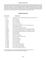
NetworX NX-8 Control/Communicator Installation Manual Table of Contents General Description 2 Ordering Information 2 Feature Definitions 3-6 Programming the LED Keypads 7 Programming the NX-8 9-11 Types of Programming Data 9-11 Enrolling the Modules & Keypads 11 L Quick Start Installations - GE NX-8 | Installation Manual - Page 2
NX-8 Control, NX-108E LED Keypad, & 16.5V 25VA Transformer NX-8 Control Only 8 Zone LED Keypad 16 Zone LED Keypad 24 Zone LED Keypad Alphanumeric LCD Keypad Zone Doubling Kit (Includes 100 3.74k and 100 6.98k resistors) 16 Zone Expander Module Smart Power Supply and Buss Extender 8 Zone Wireless - GE NX-8 | Installation Manual - Page 3
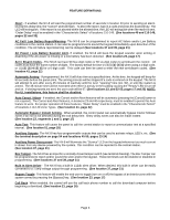
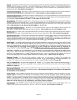
(See location 41, page 22) Automatic Arming - If programmed, the NX-8 will Auto Arm at a specified time. At this time, the keypad will beep for 50 seconds before the panel arms. The arming process will be stopped if a code is entered on the keypad. The NX-8 will attempt to arm after every 45 minutes - GE NX-8 | Installation Manual - Page 4
the system, if the panel is not disarmed before the entry delay expires. The alarm report will also be sent. Even if this feature is not enabled, the siren will sound if any entry/exit zone is faulted at the instant the exit delay expires. (See location 23, page 17) Expander Trouble- The NX-8 will - GE NX-8 | Installation Manual - Page 5
be programmed as a keyswitch zone. If this is done, a momentary short on this zone will arm/disarm the control. If opening/closing reports are sent, the user code will be 99. (See "Default Zone Types", page 18) LED Extinguish- This feature will extinguish all LED=s on the keypad, except the "Power - GE NX-8 | Installation Manual - Page 6
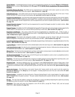
faulted zone(s) will be displayed on the LCD keypad. It will also be entered into alarm memory and the internal log. To exit at any time during this mode, enter a user code. Otherwise the AWalk-Test Mode@ will automatically exit after 15 minutes. (See location 41, page 22) Wireless Sensor Missing - GE NX-8 | Installation Manual - Page 7
there is a system trouble, pressing [r]-[2] will still show the service menu.) Enable multi-partition viewing (enables temporary viewing of all partitions by pressing [r]-[1]-[partition number]) [r]-[9]-[4] Set Keypad Number and Partition 1) Enter [r]-[9]-[4]-[program code]- The "Service" LED and - GE NX-8 | Installation Manual - Page 8
Level Program. NOTE: Any master arm/disarm code can add or change a user code if the master code has access to the same partitions as the code being added/changed. Consequently, when programming the user codes for a partitioned system, leave at least one code (can be "go to program code" if - GE NX-8 | Installation Manual - Page 9
Mode and ready to select the module to program. SELECTING THE MODULE TO PROGRAM: Since all modules connected to the NX-8 are programmed through the keypad, the module you are programming should be the first entry. To program the NX-8 Control Panel, enter [0]-[#]. The [0] is the module number of the - GE NX-8 | Installation Manual - Page 10
PROGRAMMING EXAMPLE TO BE INSERTED HERE. Page 10 - GE NX-8 | Installation Manual - Page 11
its memory, the presence of all keypads, zone expanders, wireless receivers, and any other module connected to the data terminal. This allows these modules to be supervised by the control panel. To enroll the modules, enter the Program Mode of the NX-8 control panel as described on page 9. When the - GE NX-8 | Installation Manual - Page 12
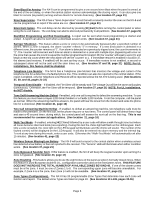
should be programmed as "0" (disabling all options). LOCATION 4 - EVENTS REPORTED TO PHONE # 1 (2 segments, feature selection data) Segment 1: 1 = Alarms and Alarm Restores. 2 = Opening and Closings. 3 = Zone Bypass and Bypass Restores. 4 = Zone Trouble and Trouble Restores. 5 = Power Fail, Low - GE NX-8 | Installation Manual - Page 13
unprogrammed, account code 1 will be used when the second phone number is dialed. L LOCATION 8 - COMMUNICATOR FORMAT FOR PHONE # 2 (1 segment, numerical data) Location 8 contains the communicator format used to transmit to the receiver connected to Phone #2. Consult the instruction manual for your - GE NX-8 | Installation Manual - Page 14
Reports. 8 = Start and End programing, Download complete. Segment 2: 1 = Zone and Box Tamper and Tamper Restore. 2 = Auxiliary Power Overcurrent and Ground Fault and Restore for both. 3 = Sensor Missing and Restore. 4 = Sensor Low Battery and Restore. 5 = Expander Trouble and Restore. 6 = Fail To - GE NX-8 | Installation Manual - Page 15
on the event type (such as alarm, open/close, etc programming, Download complete. Segment 2: 1 = Zone and Box Tamper and Tamper Restore. 2 = Auxiliary Power Overcurrent and Ground Fault and Restore for both. 3 = Sensor Missing and Restore. 4 = Sensor Low Battery and Restore. 5 = Expander Trouble - GE NX-8 | Installation Manual - Page 16
(8 segments, numerical data) Location 19 contains the eight digit access code the NX-8 must receive from the downloading software before the panel will permit downloading to occur. The factory default code is 84800000. L LOCATION 20 - NUMBER OF RINGS TO ANSWER (1 segment, numerical data) Location - GE NX-8 | Installation Manual - Page 17
to the user from the keypad of the system. In addition Keypad Multiple Code Attempt Tamper feature. Segment 2 : 1 - On enables the LED Extinguish feature. 2 - On enables the Require Code for Bypassing feature. 3 - On enables the Zone Bypassed Sounder Alert feature. 4 - On enables the AC Power - GE NX-8 | Installation Manual - Page 18
will enable the Automatic Bypass or Instant mode if so programmed. 24-HOUR SILENT SUPERVISED- Creates an instant silent alarm regardless of the armed state of the control panel. It will display on the keypad. KEYSWITCH ZONE - This zone type will arm and disarm the partition or partitions of the - GE NX-8 | Installation Manual - Page 19
" a zone, program the zone in "Partition Select" as zero (0) in all partitions and do not use end-of-line resistors. L LOCATION 25 - ZONES 1-8 ZONE TYPE (8 segments, numerical data) Location 25 contains the Zone Type for zones 1-8. Segment 1 is for zone 1, and Segment 8 is for zone 8. Default Zone - GE NX-8 | Installation Manual - Page 20
31 - ZONES 25-32 ZONE TYPE GROUP (8 segments, numerical data) Location 31 contains the Zone Type for zones 25-32. Segment 1 is for zone 25, Segment 8 is for zone 32. Default Zone Types are found in the table on page 18. To customize a Zone Type, see page 33. LOCATION 32 - PARTITION SELECT, ZONES 25 - GE NX-8 | Installation Manual - Page 21
On if keypad sounds upon AC Power Failure. 4 - On if keypad sounds when a Low Battery is detected. 5 - On if keypad sounds during Cross Zone trip time. 6 - On if keypad sounds for zone and box tampers. 7 - Reserved. 8 - On if keypad sounds for expander trouble (required for UL installations). Page - GE NX-8 | Installation Manual - Page 22
Program Code" as an arm only code. 3 - On enables "Go To Program Code" as an arm only after closing. 4 - On enables "Go To Program Code" as a master arm/disarm code (can change user codes) 5 - On enables "Go To Program Code" as an arm/disarm code. 6 - On enables "Go To Program Code" to bypass zones - GE NX-8 | Installation Manual - Page 23
MUST CONTAIN SIX (6) DIGITS. If the 6-digit option is not enabled in location 41, the last 2 digits will be ignored. If the duress code is programmed, it will work for all partitions. LOCATION 45 - AUXILIARY OUTPUT 1-4 PARTITION SELECTION (4 segments, feature selection data) Location 45 is used to - GE NX-8 | Installation Manual - Page 24
Alarm Beeping Keypad Code Entry (See note below) Key FOB Function 1 Key FOB Function 2 ˜ Events 49 & 50 require NX-408, NX-416, or NX-448 wireless receivers to operate. / If set to follow condition, these events will be 1 second. Notes : When Event 48 is programmed, it is possible to program a user - GE NX-8 | Installation Manual - Page 25
24 hour format the NX-8 enables codes designated as arm only after closing. This time is only valid on those days programmed in location 54. 1, and segment 8 is for partition 8. If a zone is faulted when the panel tries to auto arm, the zone will be bypassed. Segments 1-8: 1 - Auto Arming on - GE NX-8 | Installation Manual - Page 26
) Location 56 contains the event code for any zone "Restore" for a 4+2 format. The digit programmed in this location will be sent as the tens digit in place of the alarm event code. The zone ID will always be reported as the ones digit of the zone number (i.e. 9 for zone 29). This location contains - GE NX-8 | Installation Manual - Page 27
code for a zone "Trouble" for a 4+2 format. The digit programmed in this location will be sent as the tens digit. The zone ID will always be reported as the zone number (i.e. 9 for zone contains the ones digit. LOCATION 64 - KEYPAD AUXILIARY 2 COMMUNICATOR CODE, SLOW SPEED FORMATS ONLY (2 segments, - GE NX-8 | Installation Manual - Page 28
. LOCATION 66 - KEYPAD MULTIPLE CODE ENTRY TAMPER COMMUNICATOR CODE, SLOW SPEED FORMATS ONLY CODES, SLOW SPEED FORMATS ONLY (4 segments, numerical data) Location 73 contains the tens and ones digits for a 4+2 format that will be sent if "Ground Fault Reporting" is enabled, and the NX-870 is installed - GE NX-8 | Installation Manual - Page 29
Expander Trouble Reporting". Segment 3 contains the tens digit of the "Expander Trouble Restore". Segment 4 contains the ones digit of the "Expander Trouble Restore". LOCATION 75 - FAIL TO COMMUNICATE COMMUNICATOR CODE ones digit of the user number that did the opening. If the user is greater than 9, - GE NX-8 | Installation Manual - Page 30
account code. If the account code is 6 digits long program all 6 segments. LOCATION 90 - PARTITION 2 FEATURE AND REPORTING SELECTIONS (3 segments, feature selection data) Location 90 is used to enable certain features that can be accessed or are visible to the user from the keypad of the system. In - GE NX-8 | Installation Manual - Page 31
. If the account code is 6 digits long, program all 6 segments. LOCATION 99 - PARTITION 5 FEATURE AND REPORTING SELECTIONS (3 SEGMENTS, NUMERICAL DATA) Location 99 is used to enable certain features that can be accessed or are visible to the user from the keypad of the system. In addition, certain - GE NX-8 | Installation Manual - Page 32
. If the account code is 6 digits long, program all 6 segments. LOCATION 102 - PARTITION 6 FEATURE AND REPORTING SELECTIONS (3 segments, feature selection data) Location 102 is used to enable certain features that can be accessed or are visible to the user from the keypad of the system. In addition - GE NX-8 | Installation Manual - Page 33
149 ARE USED TO CHANGE THE ZONE TYPES (Configurations) AS LISTED IN THE TABLE ON PAGE 18. THESE LOCATIONS ARE CONSIDERED ADVANCED PROGRAMMING AND SHOULD ONLY BE CHANGED WITH A THOROUGH UNDERSTANDING OF THE OPERATION OF EACH BIT. LOCATION 110 - ZONE TYPE 1 ALARM EVENT CODE (1 segment, numerical data - GE NX-8 | Installation Manual - Page 34
- ZONE TYPE 4 ALARM EVENT CODE (1 segment, numerical data) Location 116 contains the event code sent for a Contact ID or SIA report. The desired event code should be chosen from the list on page 52. The zone ID will be that zone that is in alarm. If 4+2 format is being used, the number programmed in - GE NX-8 | Installation Manual - Page 35
- ZONE TYPE 12 ALARM EVENT CODE (1 segment, numerical data) Location 132 contains the event code sent for a Contact ID or SIA report. The desired event code should be chosen from the list on page 52.The zone ID will be that zone that is in alarm. If 4+2 format is being used, the number programmed in - GE NX-8 | Installation Manual - Page 36
- ZONE TYPE 17 ALARM EVENT CODE (1 segment, numerical data) Location 142 contains the event code sent for a Contact ID or SIA report. The desired event code should be chosen from the list on page 52. The zone ID will be that zone that is in alarm. If 4+2 format is being used, the number programmed - GE NX-8 | Installation Manual - Page 37
To Program) Segment #2 (Circle Numbers To Program) 1 Alarms and Restores 1 Tampers 2 Open/Close 2 Short Circuit & Ground Fault 3 Bypass 3 Sensor Lost 4 Zone Trouble 4 Sensor Low Battery 5 Power Trouble (AC Failure or Low Battery) 5 Expander Trouble 6 Siren & Telephone Fault 6 Failure To - GE NX-8 | Installation Manual - Page 38
To Program) 1 Alarms and Restores 2 Open/Close 3 Bypass 4 Zone Trouble 5 Power Trouble (AC Failure or Low Battery) 6 Siren & Telephone Fault 7 Test Reports 8 Program, Download, & Log Full 1 Tampers 2 Short Circuit & Ground Fault 3 Sensor Lost 4 Sensor Low Battery 5 Expander Trouble 6 Failure To - GE NX-8 | Installation Manual - Page 39
control panel 5 Lock out local programming 6 Lock out communicator programming user code for bypassing zones 3 Bypass sounder alert 4 AC power/low battery sounder alert 5 Enables bypass toggle 6 Enables silent auto arm 7 Enables automatic instant 8 Reserved 1 Open/Close 2 Bypass 3 Restore 4 Trouble - GE NX-8 | Installation Manual - Page 40
LOC PG DESCRIPTION DEFAULT PROGRAMMING DATA L 27 19 ZONES 9-16, ZONE TYPES 6-6-6-6-6-6-6-6 ________ 28 19 ZONES 9-16, PARTITION SELECTION (Segment 1=Zone 9 thru Segment 8=Zone 16) Segments 1 2 3 4 5 6 7 8 Partition #1 1 1 1 1 1 1 1 1 Partition #2 2 2 2 2 2 2 2 2 - GE NX-8 | Installation Manual - Page 41
Battery report enabled. 4 Auxiliary power over current report enabled. 5 Siren supervision report enabled. 6 Telephone Line Cut report enabled. 7 Ground Fault Detection report enabled. 8 Expander trouble report enabled. Segment #4 (Circle numbers to program) 1 Failure To Communicate report enabled - GE NX-8 | Installation Manual - Page 42
the Disarmed state. 3 Keypad sounds upon AC Power Failure. 4 Keypad sounds upon Low Battery Detection. 5 Keypad sounds during Cross Zone Trip Time. 6 Keypad sounds for Tamper Alarm. 7 Reserved. 8 Keypad sounds for expander trouble (required for UL). L 40 22 SYSTEM TIMERS Segment #1 Dynamic Battery - GE NX-8 | Installation Manual - Page 43
Go To Program Code" as an arm only code. 3 Enables "Go To Program Code" as an arm only after closing. 4 Enables "Go To Program Code" as a master arm/disarm code (can change user codes) 5 Enables "Go To Program Code" as an arm/disarm code. 6 Enables "Go To Program Code" to bypass zones. 7 Enables "Go - GE NX-8 | Installation Manual - Page 44
L 51 52 53 25 AUTOTEST CONTROL Segment #1: Program a "1" if the interval is hours, a "0" if in days. Add a A2" to suppress the daily test or a A3" to suppress the hourly test. Segment #2: Program the autotest interval from 1-255 days or hours. Segment #3: Program the autotest report in 24 hour - GE NX-8 | Installation Manual - Page 45
#1 Trouble Code 0 _ Segment #2: Partition #2 Trouble Code 0 _ Segment #3: Partition #3 Trouble Code 0 _ Segment #4: Partition #4 Trouble Code 0 _ Segment #5: Partition #5 Trouble Code 0 _ Segment #6: Partition #6 Trouble Code 0 _ Segment #7: Partition #7 Trouble Code 0 _ Segment - GE NX-8 | Installation Manual - Page 46
74 29 EXPANDER TROUBLE / EXPANDER TROUBLE RESTORE 0-0-0-0 75 29 FAILURE TO COMMUNICATE 0-0 76 29 LOG FULL COMMUNICATOR CODE 0-0 77 29 OPENING CODE COMMUNICATOR CODE Segment #1: Opening Code for Partition #1 Segment #2: Opening Code for Partition #2 Segment #3: Opening Code for Partition - GE NX-8 | Installation Manual - Page 47
Tamper 1 LED Extinguish enable 2 Require user code for bypassing 3 zones 4 Bypass sounder alert 5 AC Power/Low Battery sounder alert 6 Enables Bypass toggle 7 Enables Silent Auto Arm 8 Enables Automatic Instant Reserved 1 Open/Close 2 Bypass 3 Restore 4 Trouble 5 Tamper 6 Cancel 7 Recent Closing - GE NX-8 | Installation Manual - Page 48
Auxiliary 2 8 Multi Keypress Tamper 1 LED Extinguish enable 1 Open/Close 2 Require user code for bypassing zones 2 Bypass 3 Bypass sounder alert 3 Restore 4 AC Power/Low Battery sounder alert 4 Trouble 5 Enables Bypass toggle 5 Tamper 6 Enables Silent Auto Arm 6 Cancel 7 Enables Automatic - GE NX-8 | Installation Manual - Page 49
Arm 1 LED Extinguish enable 1 Open/Close 2 Re-Exit 2 Require user code for bypassing zones 2 Bypass 3 Auto Bypass 3 Bypass sounder alert 3 Restore 4 Silent Panic 4 AC Power/Low Battery sounder alert 4 Trouble 5 Audible Panic 5 Enables Bypass toggle 5 Tamper 6 Auxiliary 1 6 Enables - GE NX-8 | Installation Manual - Page 50
SELECT 128 34 ZONE TYPE 10 ALARM EVENT CODE 129 35 ZONE TYPE 10 CHARACTERISTIC SELECT 130 35 ZONE TYPE 11 ALARM EVENT CODE 131 35 ZONE TYPE 11 CHARACTERISTIC SELECT 132 35 ZONE TYPE 12 ALARM EVENT CODE 133 35 ZONE TYPE 12 CHARACTERISTIC SELECT 134 35 ZONE TYPE 13 ALARM EVENT CODE 135 35 ZONE TYPE 13 - GE NX-8 | Installation Manual - Page 51
OC DOWNLOAD COMPLETE 412 RS START PROGRAM 627 LB END PROGRAM 628 LX GROUND FAULT 310 GF GROUND FAULT RESTORE 310 GK RECENT CLOSE (user number) 401 CR EXIT ERROR (user number) 457 EE EVENT LOG FULL 605 JL FAIL TO COMMUNICATE 354 RT EXPANDER TROUBLE (device number) 333 ET - GE NX-8 | Installation Manual - Page 52
NX-8 has the ability to report SIA level 1 transmissions to either or both phone numbers. Each report in SIA consists of an Event Code and a Zone or User ID. The Zone ID will be the zone number that is in alarm. The event code will come from the chart below and be programmed in the zone type event - GE NX-8 | Installation Manual - Page 53
EXPANDER TROUBLE The tables below list the device numbers that will be reported for trouble conditions. Device NX-8 Control Panel NX-534E Two Way Listen-In NX-540E "Operator" NX-580E Cellemetry Interface NX-870E Fire Supervision Device # reported 0 See page 52 for possible report codes - GE NX-8 | Installation Manual - Page 54
NX-8 WIRING DIAGRAM For CE labeled products, please refer to page 57 for specific electrical requirements. Page 54 - GE NX-8 | Installation Manual - Page 55
terminal on the keypads and the expanders. Connect to the POS terminal on the keypads and the expanders. This terminal and AUX PWR + are limited to 1 amp total current when added together. Smoke detector power 12VDC, 1.5 amps maximum (For those jurisdictions which allow the Priority zone to be used - GE NX-8 | Installation Manual - Page 56
it is the customers equipment that is not functioning properly. If the problem is with the device, the customer shall discontinue use until it is repaired. EQUIPMENT INFORMATION MANUFACTURER OF CONNECTING EQUIPMENT: CADDX CONTROLS, INC. FCC REGISTRATION NUMBER: GCQUSA-31771-AL-T, RINGER EQUIVALENCE - GE NX-8 | Installation Manual - Page 57
Caddx Controls Manufacturer's Address: 1420 North Main Street Gladewater TX 75647 EU Representative: Interlogix Europe Product Identification Product: Model: Brand: NetworX NX-8 CADDX of problems, you should contact your equipment supplier in the first instance. Electrical Requirements This - GE NX-8 | Installation Manual - Page 58
expander trouble must activate keypad sounder (Loc 39, Segment 1, LED 8) ! For Canadian installations, the class II transformer secure tab shall not be employed. MINIMUM SYSTEM CONFIGURATIONS FOR UL INSTALLATIONS (Residential Fire, Residential Burglary, Commercial Burglary) ! The NetworX NX-8 panel - GE NX-8 | Installation Manual - Page 59
personnel should thoroughly read and understand the installation instructions and the users manuals for the panel and all the accessories to be included with the system before attempting to install a security system. WARNING! Replace only with Panasonic #LC12V4BP or Yuasa #NP4-12 battery - GE NX-8 | Installation Manual - Page 60
SYSTEM NOTES Page 60 - GE NX-8 | Installation Manual - Page 61
LED KEYPAD Current Draw Zones Normal w/o Sounder Dimensions NX-148 LCD KEYPAD Current Draw w/o Sounder Dimensions METAL ENCLOSURE DIMENSION SHIPPING WEIGHT 16.5 VAC 25, 40, or 50 VA Transformer 12 VDC Regulated 500 mA 12 VDC Regulated 1 AMP 12 VDC Regulated 2 AMPS + Control Panel Power 300
-
 1
1 -
 2
2 -
 3
3 -
 4
4 -
 5
5 -
 6
6 -
 7
7 -
8
-
9
-
10
-
11
-
12
-
13
-
14
-
15
-
16
-
17
-
18
-
19
-
20
-
21
-
22
-
23
-
24
-
25
-
26
-
27
-
28
-
29
-
30
-
31
-
32
-
33
-
34
-
35
-
36
-
37
-
38
-
39
-
40
-
41
-
42
-
43
-
44
-
45
-
46
-
47
-
48
-
49
-
50
-
51
-
52
-
53
-
54
-
55
-
56
-
57
-
58
-
59
-
60
-
61
 |
 |

NetworX NX-8
Control/Communicator
Installation Manual
Table of Contents
GE Interlogix
Gladewater, Texas
1-800-727-2339
General Description
.............................................................................................
2
Ordering Information
...........................................................................................
2
Feature Definitions
..........................................................................................
3-6
Programming the LED Keypads
........................................................................
7
Programming the NX-8
..................................................................................
9-11
Types of Programming Data
.........................................................................
9-11
Enrolling the Modules & Keypads
....................................................................
11
L
Quick Start Installations
............................................................................
11
Communicator Formats
....................................................................................
12
Reporting Events to Phone #1, #2, & #3
....................................................
12-15
Default Zone Types
............................................................................................
18
Zone Doubling
....................................................................................................
21
Programming the Outputs
..........................................................................
23-24
Programming Worksheets
..........................................................................
37-50
SIA and Contact ID Formats
.......................................................................
51-52
Expander Trouble Reporting Information
........................................................
53
Wiring Diagram
..................................................................................................
54
Terminal Description
.........................................................................................
55
Telephone Interface Information
......................................................................
56
CE Notice / Declaration
.....................................................................................
57
Underwriters Laboratories Information
...........................................................
58
Specifications
................................................................................................
Back