GE NX-8 Installation Manual - Page 55
When Connected To Nx-8, When Connected To Nx-320 - networx
 |
UPC - 782136401462
View all GE NX-8 manuals
Add to My Manuals
Save this manual to your list of manuals |
Page 55 highlights
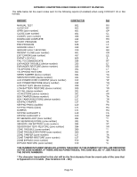
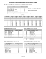
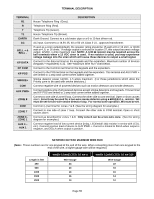
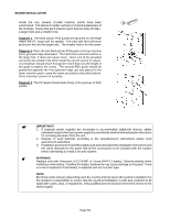
TERMINAL DESCRIPTION TERMINAL R1 R T T1 EARTH AC BELL + & BELL - KP DATA KP COM KP POS SMOKE+ COM AUX PWR+ ZONE 8 COM ZONE 7 ZONE 6 ZONE 1 AUX 4 - AUX 1 DESCRIPTION House Telephone Ring (Grey). Telephone Ring (Red). Telephone Tip (Green). House Telephone Tip (Brown). Earth Ground. Connect to a cold water pipe or a 6 to 10 foot driven rod. AC input. Connect to a 16.5V 25, 40 or 50 VA Class ll U.L. approved transformer. If used as a siren output(default), the speaker rating should be 15 watt at 8 or 16 ohm, or 30/40 watt at 4, 8, or 16 ohms. If voltage output is selected in location 37, this output becomes voltage output, 12VDC, 1 Amp maximum load. NOTE: A 3.3K Ω resistor may be required across the bell terminals when a 12 VDC siren is used. If no resistor is used, you may experience voltage leakage into the siren which will cause these devices to output a small signal. Connect to the data terminal on the keypads and the expanders. Maximum number of devices (keypads + expanders) is 32. See AMaximum Wire Run@ chart below. Connect to the Common terminal on the keypads and the expanders. Connect to the POS terminal on the keypads and the expanders. This terminal and AUX PWR + are limited to 1 amp total current when added together. Smoke detector power 12VDC, 1.5 amps maximum (For those jurisdictions which allow the Priority zone to be used with smoke detectors.) Connect negative wire of powered devices such as motion detectors and smoke detectors. Connect positive wire of all powered devices except smoke detectors and keypads. This terminal and KP POS are limited to 1 amp total current when added together. Connect to one side of zone 8 loop. Connect the other side to com terminal. Open or short causes alarm. Zone 8 may be used for a two-wire smoke detector using a 680 Ω E.O.L. resistor. W3 must be set for two-wire smoke detector loop. For normal zone operation, W4 must be set. Common (-) terminal for zones 7 & 8. (See the wiring diagram for examples.) Connect to one side of zone 7 loop. Connect the other side to COM terminal. Open or short causes alarm. Connect as described for zones 7 & 8. Only zone 8 can be a two-wire zone. (See the wiring diagram for examples.) Connect negative lead of low current device [relay, LED(install 1kΩ resistor in series with LED), etc.]. Connect positive lead of device to AUX PWR +. Current is limited to 50mA when output is negative, and 250FA when output is positive. NETWORX KEYPAD MAXIMUM WIRE RUN (Note: These numbers are for one keypad at the end of the wire. When connecting more than one keypad to the end of the wire, a higher gauge wire will be required.) Length in feet 250 500 1000 1500 2500 WHEN CONNECTED TO NX-8 Wire Gauge 24 20 18 16 14 WHEN CONNECTED TO NX-320 Wire Gauge 22 18 16 14 12 Page 55
-
 1
1 -
2
-
3
-
4
-
5
-
6
-
7
-
8
-
9
-
10
-
11
-
12
-
13
-
14
-
15
-
16
-
17
-
18
-
19
-
20
-
21
-
22
-
23
-
24
-
25
-
26
-
27
-
28
-
29
-
30
-
31
-
32
-
33
-
34
-
35
-
36
-
37
-
38
-
39
-
40
-
41
-
42
-
43
-
44
-
45
-
46
-
47
-
48
-
49
-
 50
50 -
 51
51 -
 52
52 -
 53
53 -
 54
54 -
 55
55 -
 56
56 -
 57
57 -
 58
58 -
 59
59 -
 60
60 -
61
 |
 |