Genie ChainLift 800 Owner's Manual - Page 13
ANGLE IRON ON FINISHED CEILING, UNFINISHED OR OPEN BEAM, Extra framing, not needed, NEEDED
 |
View all Genie ChainLift 800 manuals
Add to My Manuals
Save this manual to your list of manuals |
Page 13 highlights
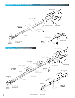
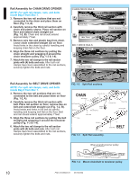
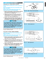
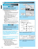
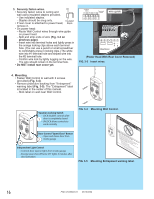
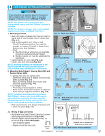
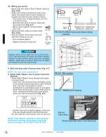
MOUNTING THE OPENER: 1. Getting started. • Position assembled rail on wall next to header bracket (Fig. 2-4). - Place material on floor under power head to protect from scratching. (A box, stool, or similar device may be needed to clear a torsion spring.) NOTE: For header bracket pins locate Bag 2 from Box 1. 2. Mounting the assembly. • Attach rail to header bracket using clevis pin and cotter pin (Fig. 2-5). • Support power head on step-ladder to prevent interference with header mounted (torsion) spring. NOTE: Before final attachment to ceiling, insure that assembly is in proper alignment (Fig. 2-4). NOTE: For nuts, bolts, and lag screws locate Bag 3 from Box 1. • On finished ceilings, locate ceiling joists or trusses using a stud finder or similar device. Attach angle iron (not provided) to joists or trusses through finish material using (provided) lag screws (Fig. 2-6). • On unfinished ceilings or open ceilings, straps may attach directly to joists or trusses. Depending on the garage construction, extra framing material (not provided) which may be required should be installed using appropriate construction techniques (Fig. 2-6). NOTE: Refer to your local building codes for appropriate construction techniques. • Attach mounting straps (not provided) to ceiling using lag bolts (Fig. 2-6). • Set height of power head to following (Fig. 2-6). a) Rail must clear door at door's highest point of travel. b) Rail must be level or at power head end slightly below level. • Securely tighten power head mounting bolts and nuts. • Carefully raise and lower door manually. Ensure door does not contact any section of power head or rail. • Check that rail clamp bolts and nuts are tight. • DO NOT PLUG OPENER IN YET! HEADER BRACKET VIEW FROM ABOVE (not to scale) NO NO YES / SÍ / OUI FIG. 2-4 Position assembly and align. CLEVIS PIN COTTER PIN (Chain drive shown) FIG. 2-5 Rail mounting to header bracket. ANGLE IRON ON FINISHED CEILING DRYWALL Attach angle iron to beams UNFINISHED OR OPEN BEAM Extra framing not needed Mounting Straps (not provided) bolts & nuts bolts & nuts Extra framing NEEDED FIG. 2-6 Mounting the power head. PN# 37026500123 05/15/2009 13
-
 1
1 -
2
-
3
-
4
-
5
-
6
-
7
-
 8
8 -
 9
9 -
 10
10 -
 11
11 -
 12
12 -
 13
13 -
 14
14 -
 15
15 -
 16
16 -
 17
17 -
 18
18 -
19
-
20
-
21
-
22
-
23
-
24
-
25
-
26
-
27
-
28
-
29
-
30
 |
 |
