Gigabyte GA-8IPXDR-E User Manual
Gigabyte GA-8IPXDR-E Manual
 |
View all Gigabyte GA-8IPXDR-E manuals
Add to My Manuals
Save this manual to your list of manuals |
Gigabyte GA-8IPXDR-E manual content summary:
- Gigabyte GA-8IPXDR-E | User Manual - Page 1
GA-8IPXDR-E Series Intel® Dual XeonTM Serverboard USER'S MANUAL Intel® Dual Xeon Processor Serverboard Rev. 1001 25A08-08IPX-F00 - Gigabyte GA-8IPXDR-E | User Manual - Page 2
Summary 6 GA-8IPXDR-E(C) Motherboard Layout 8 Chapter 2 Hardware Installation Process 9 Step 1: Install the Central Processing Unit (CPU 10 Step 1-1: Installing Motherboard to the Chassis 10 Step 1-2: CPU Installation 11 Step 1-3: CPU Heat Sink Installation 13 Step 2: Install memory modules - Gigabyte GA-8IPXDR-E | User Manual - Page 3
Table of Content Chapter 4 Technical Reference 60 GA-8IPXDR-E System Block Diagram 60 Chapter 5 Appendix 61 Appendix A: Installation 66 Appendix F: About Updateing Latest version of BIOS 66 Appendix G: IPMI Connector Pin Definition 67 Appendix H: Acronyms 68 Technical Support/RMA Sheet 70 3 - Gigabyte GA-8IPXDR-E | User Manual - Page 4
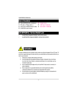
motherboard driver & utility ; SCSI Cable x 1 (Optional) ; GA-8IPXDR-E user's manual GA-8IPXDR-E Series Model List 3 GA-8IPXDR-E (Supports 533MHz / with SCSI function) 3 GA-8IPXDR-EC (Supports 533MHz / without SCSI function) WARNING! Computer motherboards and expansion cards or connectors, or - Gigabyte GA-8IPXDR-E | User Manual - Page 5
careful of your hands). In this way you can still attach the motherboard to the base without worrying about short circuits. Sometimes you may need to use the plastic springs to isolate the screw from the motherboard PCB surface, because the circuit wire may be near by the hole. - Gigabyte GA-8IPXDR-E | User Manual - Page 6
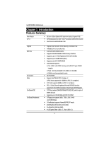
GA-8IPXDR-E(C) Motherboard Chapter 1 Introduction Features Summary Form Factor CPU y 30.5cm x 33cm Extend ATX size form factor, 8 layers PCB. y mPGA 604 socket for Intel® XeonTM processor with 512KB L2cache y Intel Prestonia 400/533MHz FSB Chipset Memory I/O Control Slots On-Board IDE On-Board - Gigabyte GA-8IPXDR-E | User Manual - Page 7
320 SCSI Chipset PS/2 Connector y PS/2 Keyboard interface and PS/2 Mouse interace BIOS y Licensed AMI BIOS, 4M bit FWH Additional Features y Wake on LAN y AC Recovery y IPMI V1.0 (Winbond BMC) y Intel® RADIOS circuits support Cards....etc. 7 - Gigabyte GA-8IPXDR-E | User Manual - Page 8
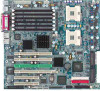
GA-8IPXDR-E(C) Motherboard GA-8IPXDR-E(C) Motherboard Layout FDD1 USB1 IPMI_CON IDE1 BIOS COM2 J20 *SCSI1 (Channel *SCSI2 (Channel B) A) ICH3-S IDE2 *SCSI 7902W CLR_COMS BT1 CPU1 (Install First) ATX2 ATX1 ATX3 CN1 USB2 COM1LPT VGA LAN1 LAN2 Note that * indicates for GA-8IPXDR-E Only 8 - Gigabyte GA-8IPXDR-E | User Manual - Page 9
: Step 1- Install the Central Processing Unit (CPU) Step 2- Install memory modules Step 3- Install expansion cards Step 4- Connect ribbon cables, cabinet wires, and power supply Step 5- Setup BIOS software Step 6- Install supporting software tools Step 4 Step 5 Step 4 Step1 Step 4 Step 3 Step - Gigabyte GA-8IPXDR-E | User Manual - Page 10
GA-8IPXDR-E(C) Motherboard Step 1: Install the Central Processing Unit (CPU) Step 1-1: Installing Motherboard to the Chassis... You may use the 4 screws which come with the mainboard to reinforce the support between Xeon CPU heat-sink on the mainboard and chassis. Step1: The 4 new mounting holes on - Gigabyte GA-8IPXDR-E | User Manual - Page 11
Step 1-2: CPU Installation Hardware Installation Process Pin1 indicator CPU Top View: Socket 603 / 400MHz CPU Botttom View: Socket 603 / 400MHz CPU Top View: Socket 604 / 533MHz CPU Bottom View: Socket 604 / 533MHz For socket 603 / 400MHz Socket Actuation Lever Pin1 indicator 1. Pull the - Gigabyte GA-8IPXDR-E | User Manual - Page 12
GA-8IPXDR-E(C) Motherboard 3. Press down the CPU socket lever and finish CPU installation. For Press down the CPU socket lever and finish CPU installation. 0 Please make sure the CPU type is supported by the motherboard. 0 If you do not match the CPU socket Pin 1 and CPU cut edge well, it will - Gigabyte GA-8IPXDR-E | User Manual - Page 13
Step 1-3: CPU Heat Sink Installation Hardware Installation Process 1. Use qualified fan approved by Intel. 2. Heat Sink 3. First step of assembling. 4. Completive picture for first step. 5. Second step of assembling. 6. Completive picture for second step. 13 - Gigabyte GA-8IPXDR-E | User Manual - Page 14
GA-8IPXDR-E(C) Motherboard 7. Fan assembly. 8. Hook one end of the cooler bracket to the CPU socket first. 9. Picture of device set on the motherboard. 0 CPU fan connector, this completes the installation. 0 Please refer to CPU heat sink user's manual for more detail installation procedure. 14 - Gigabyte GA-8IPXDR-E | User Manual - Page 15
Process Step 2: Install memory modules The motherboard has 6 dual inline memory module (DIMM) sockets, but it can only support a maximum of 3 banks DDR memory. DDR socket 1 uses 1 bank, DDR socket 2& 3 share the remaining 2 banks. The BIOS will automatically detects memory type and size. To - Gigabyte GA-8IPXDR-E | User Manual - Page 16
GA-8IPXDR-E(C) Motherboard J4 (B-1) J1 (A-1) J5 (B-2) J2 (A-2) J6 (B-3) J3 (A-3) Installation Step: 1. The DIMM slot has a notch, so the DIMM memory module can only fit in one direction. 2. Insert the DIMM memory module vertically into the DIMM slot. Then push it down. 3. Close the plastic clip at - Gigabyte GA-8IPXDR-E | User Manual - Page 17
1. Read the related expansion card's instruction document before install the expansion card into the computer. 2. Remove your computer's chassis cover, screws and slot bracket from the computer. 3. Press the expansion card firmly into expansion slot in motherboard. 4. Be sure the metal contacts - Gigabyte GA-8IPXDR-E | User Manual - Page 18
GA-8IPXDR-E(C) Motherboard Step 4: Connect ribbon cables, cabinet wires, and power supply Step 4-1: I/O Back Panel Introduction X Z Y [ \ X PS/2 Keyboard and PS/2 Mouse Connector PS/2 Mouse Connector (6 pin Female) PS/2 Keyboard Connector (6 pin Female) ¾This connector supports standard PS - Gigabyte GA-8IPXDR-E | User Manual - Page 19
Port / VGA Port (LPT/COMA/VGA) Parallel Port (25 pin Female) COMA Serial Port (9 pin Male) VGA VGA Port (15 pin Female) ¾This connector supports 1 standard COM port ,1 Parallel port and 1 VGA port. Device like printer can be connected to Parallel port ; mouse and modem etc can be connected to - Gigabyte GA-8IPXDR-E | User Manual - Page 20
GA-8IPXDR-E(C) Motherboard Step 4-2: Connectors Introduction HG S J K D I E F Q M LN P U T R C A) ATX3 B) ATX1 C) ATX2 D) BT1 E) SCSI1 F) SCSI2 G) FDD1 H) USB1 I ) IDE1 J ) IDE2 K) IPMI_CON O B A L) COM2 M) CASEOPEN N) J20 (Front Panel) O) J30 P) J31 Q) J32 R) J33 S) J34 T) J18 ( - Gigabyte GA-8IPXDR-E | User Manual - Page 21
power cord should only be connected to your power supply unit after ATX power cable and other related devices are firmly connected to the mainboard. Connector Introduction PIN No. 1 2 3 4 5 6 7 8 9 10 11 12 13 14 15 16 17 18 19 20 21 22 23 24 Definition +3.3V +3.3V GND +5V GND +5V - Gigabyte GA-8IPXDR-E | User Manual - Page 22
GA-8IPXDR-E(C) Motherboard C) ATX2 (+12V Power Connector) 43 21 Pin No. 1 2 3 4 Definition GND GND +12V +12V ¾This connector (ATX +12V) is used only for CPU Core Voltage. O/Q ) J30/J32 (CPU FAN Connector) J32 damaged by overheating.The CPU fan connector supports Max. current up to 600mA . 22 - Gigabyte GA-8IPXDR-E | User Manual - Page 23
F/O) J33/J34 (System FAN Connector) J33 1 Connector Introduction Pin No. 1 2 3 Definition GND +12v/Control Sense J34 Pin No. Definition 1 GND 2 +12v/Control 3 Sense 1 P) J31 (Power FAN Connector) Pin No. Definition 1 GND 2 +12v/Control 1 3 Sense 23 - Gigabyte GA-8IPXDR-E | User Manual - Page 24
GA-8IPXDR-E(C) Motherboard T) J18 (Wake On LAN Connector) 1 Pin No. 1 2 3 Definition +5VSB GND Signal L) COM 2 Connector 1 Pin No. 1 2 3 4 5 6 7 8 9 10 Definition NDCDB NSINB NSOUTB NDTRB GND NDSRBNRTSBNCTSBNRIB- NC 24 - Gigabyte GA-8IPXDR-E | User Manual - Page 25
E/F) SCSI1/2 Connector Connector Introduction SCSI 1 SCSI 2 I/J) IDE1/IDE2 [IDE1 / IDE2 Connector(Primary/Secondary)] IDE2 1 1 IDE1 ¾Important Notice: Please connect first harddisk to IDE1 and connect CDROM to IDE2.The red stripe of the ribbon cable must be the same side with the Pin1. 25 - Gigabyte GA-8IPXDR-E | User Manual - Page 26
GA-8IPXDR-E(C) Motherboard G) FDD1 (Floppy Connector) 1 33 2 Floppy 34 M) CASE OPEN 1 Pin No. Definition 1 Signal 2 GND 26 - Gigabyte GA-8IPXDR-E | User Manual - Page 27
GA-8IPXDR-E(C) Motherboard N) J20 (Front Panel Connector-- Power button and Power LED) 1 20 Pin No. 17 18 19 20 Definition PWR LED+ PWR LEDPWR BTN+ PWR BTN- H) USB1 (Front USB Connector) 1 Be careful with the polarity of the front panel USB connector. Check the pin assignment while you connect - Gigabyte GA-8IPXDR-E | User Manual - Page 28
GA-8IPXDR-E(C) Motherboard K) IPMI_CON (IPMI Connector) ¾IPMI module is an optional device for customer to purchase. ¾For the IPMI connector pins definition, please refer to Appendix G. 2 70 1 69 D) the manufacturer. ™ Dispose of used batteries according to the manufacturer's instructions. 28 - Gigabyte GA-8IPXDR-E | User Manual - Page 29
K) F_PANEL connector Connector Introduction JP_SPK+ JP_HD+ JP_RST JP_HD- JP_SPK- JP_RST (Reset Button) JP_HD (HDD Active LED) JP_SPK (Speaker Connector) Open: Normal Operation Close: Reset hardware system Pin 1: LED anode(+) Pin 2: LED cathode(-) Pin 1: VCC(+) Pin 2- Pin 3: NC Pin 4: Data(-) - Gigabyte GA-8IPXDR-E | User Manual - Page 30
GA-8IPXDR-E(C) Motherboard Step 4-3: Jumper Setting Introduction 15 3 11 5 12 10 2 13 9 14 6 1 7 8 1) JP 1 2) JP 8 3) JP 9 4) JP 10 5) JP 13 6) JP 14 7) JP 15 8) JP 16 4 9) JP 17 10) JP 18 11) JP 19 12) JP 20 13) JP 21 14) JP 22 15) CLR_COMS 30 - Gigabyte GA-8IPXDR-E | User Manual - Page 31
1) JP 1 (Onboard SCSI Function) 1 1 Jumper Setting 1-2 close: SCSI Enabled (Default) 2-3 close: SCSI Disabled 2) JP 8 (Onboard VGA Functon) 1 1-2 close: VGA Enabled (Default) 1 2-3 close: VGA Disabled 3) JP 9 (Front Side USB Wake Up Function) 1 1-2 close: Front USB wake up function - Gigabyte GA-8IPXDR-E | User Manual - Page 32
GA-8IPXDR-E(C) Motherboard 4) JP 10 (Rear Side USB Wake Up Function) 1 1-2 close: Rear USB wake up function disabled (Default) 1 2-3 close: Rear USB wake up function enabled 5 / 6) JP13 / JP14 ( - Gigabyte GA-8IPXDR-E | User Manual - Page 33
Jumper Setting 7 / 8) JP15 / JP16 (P64H2#1 Secondary PCI-X max Bus Frequency Selection) For Giagbit LAN U6 1 JP15 JP15 : JP16 = 1-2 closed ; 1-2 closed ==>Set the Secondary PCI-X JP16 max Bus frequency at 133MHz (Default) 1 JP15 JP15 : JP16 = 1-2 closed ; 2-3 closed ==>Set the Secondary - Gigabyte GA-8IPXDR-E | User Manual - Page 34
GA-8IPXDR-E(C) Motherboard 11 / 12) JP19 / JP20 (P64H2#2 Secondary PCI-X max Bus Frequency Selection) For PCI-X_2 and PCI-X_4 1 JP20 JP20 JP20 : JP19 = 1-2 closed ; 1-2 closed JP19 ==>Set - Gigabyte GA-8IPXDR-E | User Manual - Page 35
15) CLR_CMOS (Clear CMOS Function) Jumper Setting 1 1-2 close: Clear CMOS 1 2-3 close: Normal (Default) You may clear the CMOS data to its default values by this jumper 35 - Gigabyte GA-8IPXDR-E | User Manual - Page 36
GA-8IPXDR-E(C) Motherboard Chapter 3 BIOS Setup BIOS Setup is an overview of the BIOS Setup Program. The program that allows users to modify the basic system configuration. This type of information is stored in battery-backed CMOS RAM so that it retains the Setup information when the power is turned - Gigabyte GA-8IPXDR-E | User Manual - Page 37
BIOS Setup GETTINGHELP Main Menu The on-line description of the highlighted setup function is exit the Help Window press . z Main This setup page includes all the items in standard compatible BIOS. z Advanced This setup page includes all the items of AMI special enhanced features. (ex: Auto - Gigabyte GA-8IPXDR-E | User Manual - Page 38
GA-8IPXDR-E(C) Motherboard Main Once you enter AMI BIOS CMOS Setup Utility, the Main Menu (Figure 1) will appear on the screen. Use arrow keys to select among the items and press to accept or enter the sub-menu. AMI BIOS NEW SETUP Utility - VERSION 3.31a Main Advanced Security Boot - Gigabyte GA-8IPXDR-E | User Manual - Page 39
BIOS Setup Floppy Drive A/B This has been installed in the computer. There are two types: auto type, and manual type. Manual type is user-definable; Auto type which will automatically detect HDD type. Note that specific IDE channel support LBA Mode This field only shows the information of Block Mode. - Gigabyte GA-8IPXDR-E | User Manual - Page 40
GA-8IPXDR-E(C) Motherboard Fast Programmed I/O Mode This field only shows the information of Fast Programmed I/O displays the following system information: the Processor type, Speed, Cache Size, Total Memory Size, Memory Resized DIMM, BIOS version, BIOS Release Date and System Product Name. 40 - Gigabyte GA-8IPXDR-E | User Manual - Page 41
Exit ` Advanced Configuration ` Chipset Configuration ` Power Management Configuration ` PCI-X Configuration `Peripheral Configuration `Hardware Monitor Configuration [Setup Help] BIOS Setup F1: Help Esc: Exit KL: Select Item IJ: Select Menu + -: Change Values F5: Setup Defaults Enter: Select - Gigabyte GA-8IPXDR-E | User Manual - Page 42
GA-8IPXDR-E(C) Motherboard Advanced Configuration AMI BIOS NEW SETUP Utility - VERSION 3.31a Main Advanced Save&Exit Figure 2-1: Advanced Configuration Advanced Configuration ` Quick Boot This setting allows BIOS to skip certain tests while booting. This will decrease the time needed to boot - Gigabyte GA-8IPXDR-E | User Manual - Page 43
to select MP (Multi Processors) system supported version. Note: Some old MPS OS support 1.1 version only. 1.4 Support MPS Version 1.4 . (Default Value) 1.1 Support MPS Version 1.1. ` Console Redirect Enable this option to remote monitoring and controlling the BIOS by the client computer. Note: If - Gigabyte GA-8IPXDR-E | User Manual - Page 44
GA-8IPXDR-E(C) Motherboard Chipset Configuration AMI BIOS NEW SETUP Utility - VERSION 3.31a Main Advanced Security Boot an Intel Pentium 4 processor at 3.06 GHz or higher, a chipset and BIOS that utilize this technology, and an operating system that includes optimizations for this technology - Gigabyte GA-8IPXDR-E | User Manual - Page 45
Setup Power Management Configuration AMI BIOS NEW SETUP Utility - VERSION 3.31a Main Advanced Security Boot Exit Power Management Configuration [Setup Help] System After AC Back PME Event Wake Up Last State - Gigabyte GA-8IPXDR-E | User Manual - Page 46
GA-8IPXDR-E(C) Motherboard PCI-X Configuration AMI BIOS NEW SETUP Utility - VERSION 3.31a Main Advanced Security Boot Exit PCI-X Configuration [Setup Help] Data Parity Error Recovery Relaxed Ordering Enabled Enabled F1: Help Esc: - Gigabyte GA-8IPXDR-E | User Manual - Page 47
3.31a Main Advanced Security Boot Exit Peripheral Configuration BIOS Setup [Setup Help] OnBoard IDE Both OnBoard FDC Parallel Port IRQ 7 Parallel Port DMA 3 USB Function Enabled USB Legacy Support Disabled OnBoard Gigabit LAN Enabled OnBoard SCSI F1: Help Esc: Exit Enabled - Gigabyte GA-8IPXDR-E | User Manual - Page 48
GA-8IPXDR-E(C) Motherboard ` OnBoard Serial Port A This option specifies the base I/O port ` OnBoard Parallel Port This option specifies the base I/O address of the parallel prot on the motherboard. 378 Enable onboard LPT port and set I/O address to 378. (Default value) 278 Enable onboard - Gigabyte GA-8IPXDR-E | User Manual - Page 49
BIOS Setup ` Parallel Port Mode This option specifies the parallel mode. Normal The normal parallel pro is used. Bi-Directional Use this setting to support bi-directional transfers on the parallel port. EPP The parallel port can be used with devices that adhere to the enhanced Parallel Port - Gigabyte GA-8IPXDR-E | User Manual - Page 50
GA-8IPXDR-E(C) Motherboard ` OnBoard Gigabit LANs This option allows user to function onboard Gigabit LANs. Enable Enables onboard Gigabit LANs. (Default Value) Disabled Disable this function. ` OnBoard SCSI - Gigabyte GA-8IPXDR-E | User Manual - Page 51
Setup AMI BIOS NEW SETUP Utility - VERSION 3.31a Main Advanced Security Boot Exit Hardware Configuration [Setup Help] Reset Case Open Status No CPU Fan Fail Alarm Disabled CPU - Gigabyte GA-8IPXDR-E | User Manual - Page 52
GA-8IPXDR-E(C) Motherboard Hardware Monitor Configuration This section provides the system hardware health information to user for reference. ` Reset Case Open Status This function provides user to stop - Gigabyte GA-8IPXDR-E | User Manual - Page 53
` CPU 0 / 1 FAN This field indicates the RPM (Ratio Per Minute) of current CPU 0/1 speed. BIOS Setup ` System FAN 1 This field indicates the RPM (Ratio Per Minute) of current system 1 fan speed. ` Power FAN 1/2 This field indicates the RPM (Ratio Per - Gigabyte GA-8IPXDR-E | User Manual - Page 54
GA-8IPXDR-E(C) Motherboard Security AMI BIOS NEW SETUP Utility - VERSION 3.31a Main Advanced Security Boot . The password typed now will clear any previously entered password from the CMOS memory. You will be asked to confirm the entered password. Type the password again and press < - Gigabyte GA-8IPXDR-E | User Manual - Page 55
BIOS Setup Set User Password You can only enter but do not have 6 characters in lengh and press . The password typed now will clear any previously entered password from the CMOS memory. You will be asked to confirm the entered password. Type the password again and press . You may also - Gigabyte GA-8IPXDR-E | User Manual - Page 56
GA-8IPXDR-E(C) Motherboard Boot AMI BIOS NEW SETUP Utility - VERSION 3.31a Main Advanced Security Boot Exit [Setup Help] Boot Device Priority 1st Floppy: 1.44 MB 31/2 2nd CD/DVD: C-540E 3rd - Gigabyte GA-8IPXDR-E | User Manual - Page 57
: Removable Device ATAPI CDROM Hard Disk Disabled (Default Value) ` OnBoard LAN Boot ROM Enabled Enable OnBoard LAN Boot ROM. Disabled Disable this function. (Default Value) BIOS Setup 57 - Gigabyte GA-8IPXDR-E | User Manual - Page 58
GA-8IPXDR-E(C) Motherboard Exit AMI BIOS NEW SETUP Utility - VERSION 3.31a Main Advanced Security Boot Exit Section: Security Once you have changed all of the set values in the BIOS setup, you should save your chnages and exit BIOS setup program. Select "Exit" from the menu bar, to display the - Gigabyte GA-8IPXDR-E | User Manual - Page 59
to store all the present setting values tha user made in this time into CMOS. Therefore, whenyou boot up your computer next time, the BIOS will re-configure your system according data in CMOS. Exit Discarding Changes This option allows user to exit system setup without changing any previous settings - Gigabyte GA-8IPXDR-E | User Manual - Page 60
GA-8IPXDR Motherboard RCehvaispitoenr H4isTtoercyhnical Reference GA-8IPXDR-E System Block Diagram 60 - Gigabyte GA-8IPXDR-E | User Manual - Page 61
Appendix RCehvaispitoenr H5istAoprypendix Appendix A: Intel Network Driver Installation (Note: Driver CD Ver. : 2.0) Insert the driver CD-title that came with your motherboard into your CD-ROM driver, the driver CD-title will auto start and show a series of Setup Wizard dialog boxes. If not, please - Gigabyte GA-8IPXDR-E | User Manual - Page 62
GA-8IPXDR-E(C) Motherboard 5.Slect either Typical or Custom Setup type and click "Next". 6. Ready to install the program. Click "Install" to begin the installation. (5) (6) Step 5. Note that user - Gigabyte GA-8IPXDR-E | User Manual - Page 63
Appendix Appendix B: INF Update Installation (Driver for chipset) Insert the driver CD-title that came with your motherboard into your CD-ROM driver, the driver CD-title will auto start and show a series of Setup Wizard dialog boxes. If not, please double click - Gigabyte GA-8IPXDR-E | User Manual - Page 64
GA-8IPXDR-E(C) Motherboard Appendix C: ATI Rage XL VGA Driver Installation Insert the driver CD-title that came with your motherboard into your CD-ROM driver, the driver CD-title will auto start and show the installation guide. If not, please double click the CD-ROM device icon in "My computer", and - Gigabyte GA-8IPXDR-E | User Manual - Page 65
Appendix Appexdix D: Adaptec SCSI Driver Installation Insert the driver CD-title that came with your motherboard into your CD-ROM driver, the driver CD-title will auto start and show the installation guide. If not, please double click the CD-ROM device icon in "My computer", and execute the setup. - Gigabyte GA-8IPXDR-E | User Manual - Page 66
GA-8IPXDR-E(C) Motherboard Appendix E: Utilites Installation Insert the driver CD-title that came with your motherboard into your CD-ROM driver, the driver CD-title will auto start and show the installation guide of BIOS To update the latest BIOS version, please go to Gigabyte Networking official - Gigabyte GA-8IPXDR-E | User Manual - Page 67
Appendix Appendix G: IPMI Connector Pin Definition Pin Definition 1 EMP Port ENABLE 2 5VSB 3 SERIAL PORT 4 SERIAL PORT 5 SERIAL PORT 6 SERIAL PORT 7 POWER OK 8 GND 9 MAIN SMBUS DATA 10 MAIN SMBUS - Gigabyte GA-8IPXDR-E | User Manual - Page 68
GA-8IPXDR-E(C) Motherboard Appendix H: Acronyms Acronyms ACPI APM AGP AMR ACR BBS BIOS CPU CMOS CRIMM CNR DMA DMI DIMM DRM DRAM DDR ECP Networking Riser Direct Memory Access Desktop Management Interface Dual Inline Memory Module Dual Retention Mechanism Dynamic Random Access Memory Double Data Rate - Gigabyte GA-8IPXDR-E | User Manual - Page 69
Instrument Digital Interface Memory Translator Hub Memory Protocol Translator Network Interface Card Operating System Original Equipment Manufacturer PCI A.G.P. Controller Power-On Self Test Peripheral Component Interconnect Rambus in-line Memory Module Special Circumstance Instructions Single Edge - Gigabyte GA-8IPXDR-E | User Manual - Page 70
GA-8IPXDR-E(C) Motherboard Technical Support/RMA Sheet Customer/Country: Company: Contact Person: E-mail Add. : Model name/Lot Number: BIOS version: O.S./A.S.: Hardware Mfs. Model name Size: Configuration CPU Memory Brand Video Card Audio Card HDD CD-ROM / DVD-ROM Modem Network
-
 1
1 -
 2
2 -
 3
3 -
 4
4 -
 5
5 -
 6
6 -
 7
7 -
8
-
9
-
10
-
11
-
12
-
13
-
14
-
15
-
16
-
17
-
18
-
19
-
20
-
21
-
22
-
23
-
24
-
25
-
26
-
27
-
28
-
29
-
30
-
31
-
32
-
33
-
34
-
35
-
36
-
37
-
38
-
39
-
40
-
41
-
42
-
43
-
44
-
45
-
46
-
47
-
48
-
49
-
50
-
51
-
52
-
53
-
54
-
55
-
56
-
57
-
58
-
59
-
60
-
61
-
62
-
63
-
64
-
65
-
66
-
67
-
68
-
69
-
70
 |
 |

USER’S MANUAL
GA-8IPXDR-E Series
Intel
®
Dual Xeon
TM
Serverboard
Intel
®
Dual Xeon Processor Serverboard
Rev. 1001
25A08-08IPX-F00