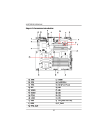
Gigabyte GA-8IPXDR-E User Manual - Page 22
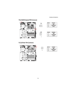
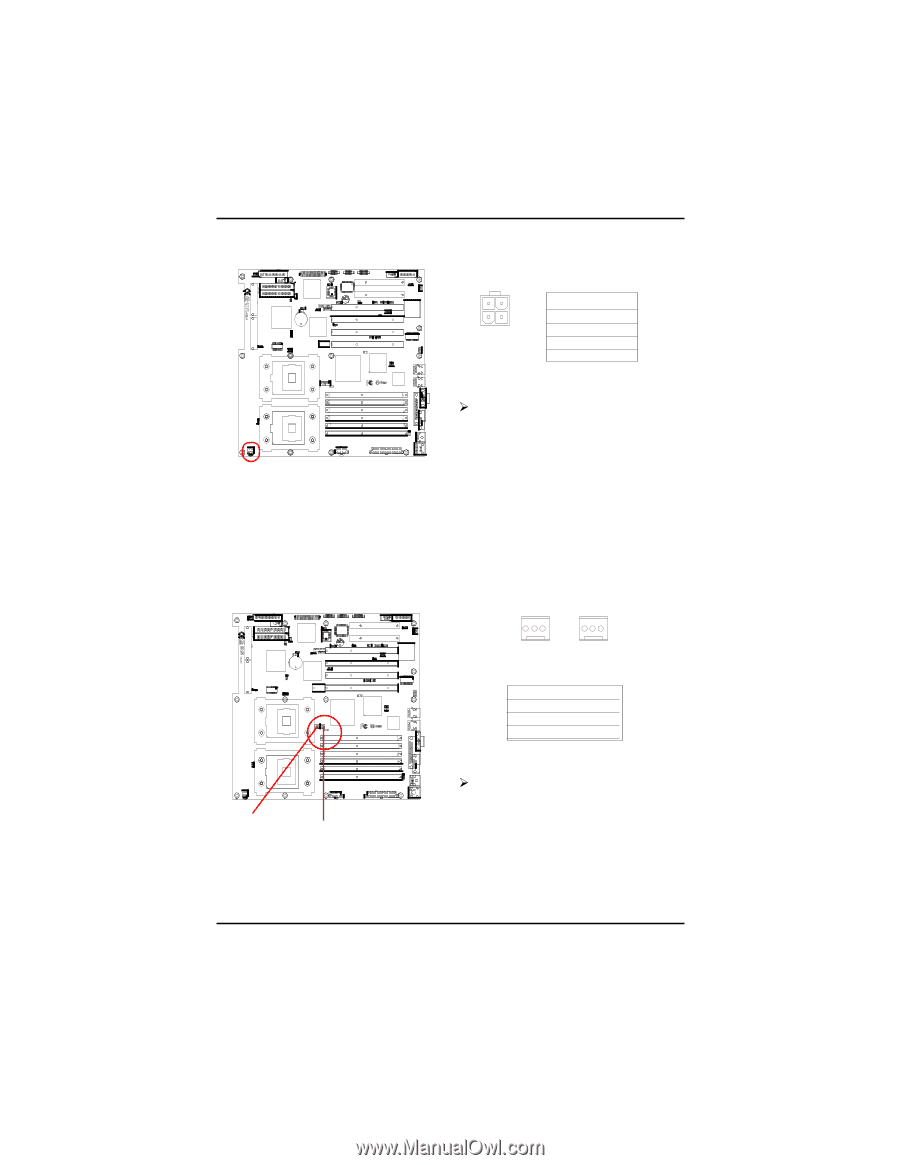
C ATX2 +12V Power Connector, O/Q J30/J32 CPU FAN Connector
 |
View all Gigabyte GA-8IPXDR-E manuals
Add to My Manuals
Save this manual to your list of manuals |
Page 22 highlights
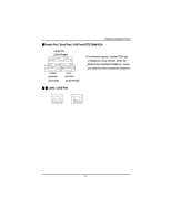
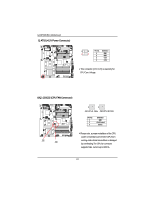
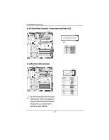
GA-8IPXDR-E(C) Motherboard C) ATX2 (+12V Power Connector) 43 21 Pin No. 1 2 3 4 Definition GND GND +12V +12V ¾This connector (ATX +12V) is used only for CPU Core Voltage. O/Q ) J30/J32 (CPU FAN Connector) J32 J30 1 1 J32:CPU1 FAN J30:CPU 0 FAN Pin No. 1 2 3 Definition GND +12v/Control Sense ¾Please note, a proper installation of the CPU cooler is essential to prevent the CPU from running under abnormal condition or damaged by overheating.The CPU fan connector supports Max. current up to 600mA . 22
-
 1
1 -
2
-
3
-
4
-
5
-
6
-
7
-
8
-
9
-
10
-
11
-
12
-
13
-
14
-
15
-
16
-
 17
17 -
 18
18 -
 19
19 -
 20
20 -
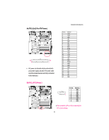 21
21 -
 22
22 -
 23
23 -
 24
24 -
 25
25 -
 26
26 -
 27
27 -
28
-
29
-
30
-
31
-
32
-
33
-
34
-
35
-
36
-
37
-
38
-
39
-
40
-
41
-
42
-
43
-
44
-
45
-
46
-
47
-
48
-
49
-
50
-
51
-
52
-
53
-
54
-
55
-
56
-
57
-
58
-
59
-
60
-
61
-
62
-
63
-
64
-
65
-
66
-
67
-
68
-
69
-
70
 |
 |
22
GA-8IPXDR-E(C) Motherboard
C) ATX2 (+12V Power Connector)
This connector (ATX +12V) is used only for
CPU Core Voltage.
Pin No.
Definition
1
GND
2
GND
3
+12V
4
+12V
1
2
3
4
O/Q ) J30/J32 (CPU FAN Connector)
Please note, a proper installation of the CPU
cooler is essential to prevent the CPU from
running under abnormal condition or damaged
by overheating.The CPU fan connector
supports Max. current up to 600mA .
Pin No.
Definition
1
GND
2
+12v/Control
3
Sense
1
J30
J32
1
J30:CPU 0 FAN
J32:CPU1 FAN