Gigabyte GA-8IPXDR-E User Manual - Page 15
Step 2: Install memory modules
 |
View all Gigabyte GA-8IPXDR-E manuals
Add to My Manuals
Save this manual to your list of manuals |
Page 15 highlights
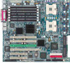
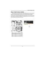
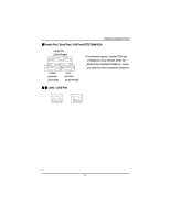
Hardware Installation Process Step 2: Install memory modules The motherboard has 6 dual inline memory module (DIMM) sockets, but it can only support a maximum of 3 banks DDR memory. DDR socket 1 uses 1 bank, DDR socket 2& 3 share the remaining 2 banks. The BIOS will automatically detects memory type and size. To install the memory module, just push it vertically into the DIMM Slot .The DIMM module can only fit in one direction due to the notch.Memory size can vary between sockets. Registered DDR Notch J4 (B-1) J1 (A-1) J5 (B-2) J2 (A-2) J6 (B-3) J3 (A-3) 15
-
 1
1 -
2
-
3
-
4
-
5
-
6
-
7
-
8
-
9
-
 10
10 -
 11
11 -
 12
12 -
 13
13 -
 14
14 -
 15
15 -
 16
16 -
 17
17 -
 18
18 -
 19
19 -
 20
20 -
21
-
22
-
23
-
24
-
25
-
26
-
27
-
28
-
29
-
30
-
31
-
32
-
33
-
34
-
35
-
36
-
37
-
38
-
39
-
40
-
41
-
42
-
43
-
44
-
45
-
46
-
47
-
48
-
49
-
50
-
51
-
52
-
53
-
54
-
55
-
56
-
57
-
58
-
59
-
60
-
61
-
62
-
63
-
64
-
65
-
66
-
67
-
68
-
69
-
70
 |
 |

Hardware Installation Process
15
Step 2: Install memory modules
The motherboard has 6 dual inline memory module (DIMM) sockets, but it can only support a
maximum of 3 banks DDR memory. DDR socket 1 uses 1 bank, DDR socket 2& 3 share the
remaining 2 banks. The BIOS will automatically detects memory type and size. To install the memory
module, just push it vertically into the DIMM Slot .The DIMM module can only fit in one direction due
to the notch.Memory size can vary between sockets.
Registered DDR
Notch
J4 (B-1)
J1 (A-1)
J5 (B-2)
J2 (A-2)
J6 (B-3)
J3 (A-3)