Gigabyte GA-EP45-DS3 Manual - Page 19
Installing the SATA Bracket
 |
View all Gigabyte GA-EP45-DS3 manuals
Add to My Manuals
Save this manual to your list of manuals |
Page 19 highlights
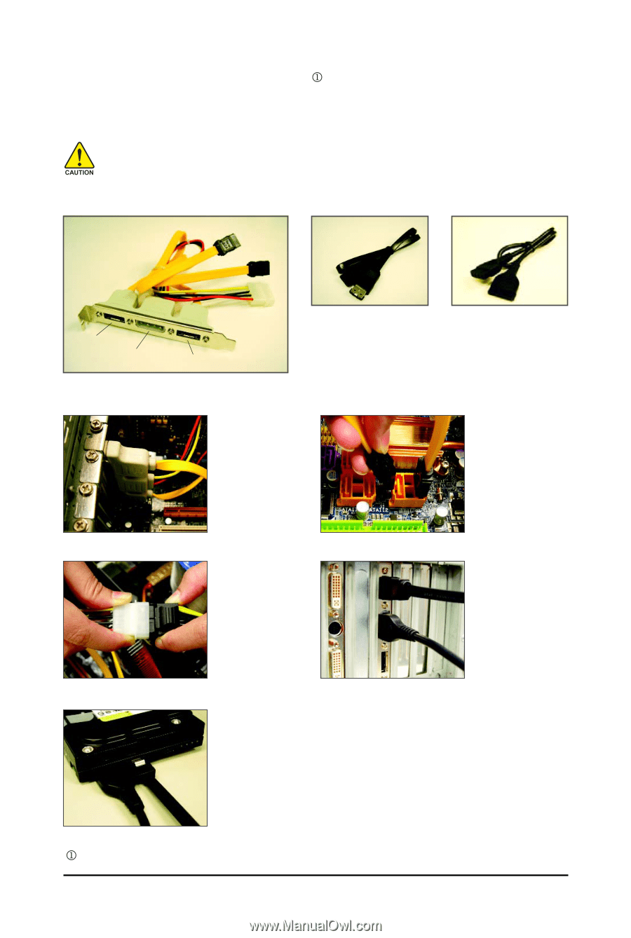
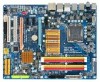
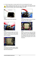
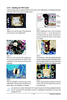
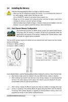
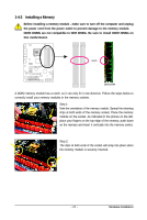
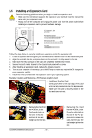
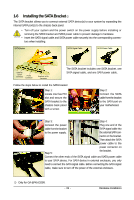
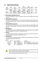
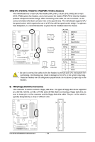
1-6 Installing the SATA Bracket The SATA bracket allows you to connect external SATA device(s) to your system by expanding the internal SATA port(s) to the chassis back panel. • Turn off your system and the power switch on the power supply before installing or removing the SATA bracket and SATA power cable to prevent damage to hardware. • Insert the SATA signal cable and SATA power cable securely into the corresponding connectors when installing. SATA Bracket SATA Signal Cable SATA Power Cable External SATA Connector Power Connector External SATA Connector The SATA bracket includes one SATA bracket, one SATA signal cable, and one SATA power cable. Follow the steps below to install the SATA bracket: Step 1: Locate one free PCI slot and secure the SATA bracket to the chassis back panel with a screw. Step 2: Connect the SATA cable from the bracket to the SATA port on your motherboard. Step 3: Step 4: Connect the power Plug one end of the cable from the bracket SATA signal cable into to the power supply. the external SATA con- nector on the bracket. Then attach the SATA power cable to the power connector on Step 5: the bracket. Connect the other ends of the SATA signal cable and SATA power cable to your SATA device. For SATA device in external enclosure, you only need to connect the SATA signal cable. Before connecting the SATA signal cable, make sure to turn off the power of the external enclosure. Only for GA-EP45-DS3R. - 19 - Hardware Installation
-
 1
1 -
2
-
3
-
4
-
5
-
6
-
7
-
8
-
9
-
10
-
11
-
12
-
13
-
 14
14 -
 15
15 -
 16
16 -
 17
17 -
 18
18 -
 19
19 -
 20
20 -
 21
21 -
 22
22 -
 23
23 -
 24
24 -
25
-
26
-
27
-
28
-
29
-
30
-
31
-
32
-
33
-
34
-
35
-
36
-
37
-
38
-
39
-
40
-
41
-
42
-
43
-
44
-
45
-
46
-
47
-
48
-
49
-
50
-
51
-
52
-
53
-
54
-
55
-
56
-
57
-
58
-
59
-
60
-
61
-
62
-
63
-
64
-
65
-
66
-
67
-
68
-
69
-
70
-
71
-
72
-
73
-
74
-
75
-
76
-
77
-
78
-
79
-
80
-
81
-
82
-
83
-
84
-
85
-
86
-
87
-
88
-
89
-
90
-
91
-
92
-
93
-
94
-
95
-
96
-
97
-
98
-
99
-
100
-
101
-
102
-
103
-
104
-
105
-
106
-
107
-
108
-
109
-
110
-
111
-
112
-
113
-
114
-
115
-
116
 |
 |