Gigabyte GA-EP45-DS3 Manual - Page 54
Onboard LAN1 Boot ROM LAN1 port
 |
View all Gigabyte GA-EP45-DS3 manuals
Add to My Manuals
Save this manual to your list of manuals |
Page 54 highlights
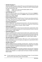
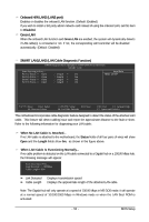
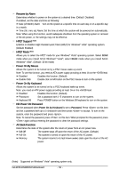
When a Cable Problem Occurs... If a cable problem occurs on a specified pair of wires, the Status field will show Short and then length shown will be the approximate distance to the fault or short. Example: Part1-2 Status = Short / Length = 2m Explanation: A fault or short might occur at about 2m on Part 1-2. Note: Part 4-5 and Part 7-8 are not used in a 10/100 Mbps environment, so their Status fields will show Open, and the length shown is the approximate length of the attached LAN cable. Onboard LAN1 Boot ROM (LAN1 port) Allows you to decide whether to activate the boot ROM integrated with the onboard LAN chip. (Default: Disabled) Onboard LAN2 Boot ROM (LAN2 port) Allows you to decide whether to activate the boot ROM integrated with the onboard LAN chip. (Default: Disabled) Onboard IDE Controller (JMicron 368 Chip) Enables or disables the IDE controller integrated in the JMicron 368 chip. (Default: Enabled) Onboard Serial Port 1 Enables or disables the first serial port and specifies its base I/O address and corresponding interrupt. Options are: Auto, 3F8/IRQ4 (default), 2F8/IRQ3, 3E8/IRQ4, 2E8/IRQ3, Disabled. Onboard Parallel Port Enables or disables the onboard parallel port (LPT) and specifies its base I/O address and corresponding interrupt. Options are: 378/IRQ7 (default), 278/IRQ5, 3BC/IRQ7, Disabled. Parallel Port Mode Selects an operating mode for the onboard parallel (LPT) port. Options are: SPP (Standard Parallel Port)(default), EPP (Enhanced Parallel Port), ECP (Extended Capabilities Port), ECP+EPP. GA-EP45-DS3R/DS3 Motherboard - 54 -
-
 1
1 -
2
-
3
-
4
-
5
-
6
-
7
-
8
-
9
-
10
-
11
-
12
-
13
-
14
-
15
-
16
-
17
-
18
-
19
-
20
-
21
-
22
-
23
-
24
-
25
-
26
-
27
-
28
-
29
-
30
-
31
-
32
-
33
-
34
-
35
-
36
-
37
-
38
-
39
-
40
-
41
-
42
-
43
-
44
-
45
-
46
-
47
-
48
-
 49
49 -
 50
50 -
 51
51 -
 52
52 -
 53
53 -
 54
54 -
 55
55 -
 56
56 -
 57
57 -
 58
58 -
 59
59 -
60
-
61
-
62
-
63
-
64
-
65
-
66
-
67
-
68
-
69
-
70
-
71
-
72
-
73
-
74
-
75
-
76
-
77
-
78
-
79
-
80
-
81
-
82
-
83
-
84
-
85
-
86
-
87
-
88
-
89
-
90
-
91
-
92
-
93
-
94
-
95
-
96
-
97
-
98
-
99
-
100
-
101
-
102
-
103
-
104
-
105
-
106
-
107
-
108
-
109
-
110
-
111
-
112
-
113
-
114
-
115
-
116
 |
 |