Gigabyte GA-M55plus-S3G Manual - Page 12
Installation of the CPU and CPU Cooler - rev 2
 |
View all Gigabyte GA-M55plus-S3G manuals
Add to My Manuals
Save this manual to your list of manuals |
Page 12 highlights
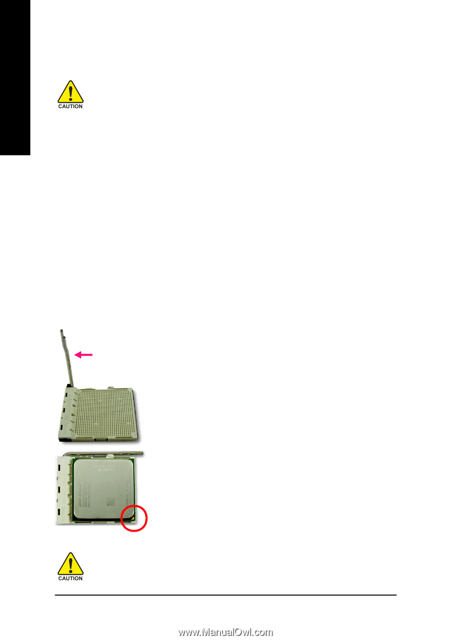
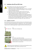
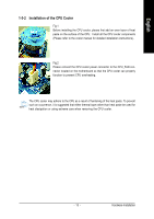
English 1-3 Installation of the CPU and CPU Cooler Before installing the CPU, please comply with the following conditions: 1. Please make sure that the motherboard supports the CPU. 2. Please take note of the pin 1 marking (the small triangle) on the CPU. If you install the CPU in the wrong direction, the CPU will not insert properly. If this occurs, please change the insert direction of the CPU. 3. Please add an even layer of heat paste between the CPU and CPU cooler. 4. Please make sure the CPU cooler is installed on the CPU prior to system use, otherwise overheating and permanent damage of the CPU may occur. 5. Please set the CPU host frequency in accordance with the processor specifications. It is not recommended that the system bus frequency be set beyond hardware specifications since it does not meet the required standards for the peripherals. If you wish to set the frequency beyond the proper specifications, please do so according to your hardware specifications including the CPU, graphics card, memory, hard drive, etc. 1-3-1 Installation of the CPU Check the CPU pins to see that none are bent. Move the socket lever to the unlocked position as shown in Fig. 1 (90o to the plane of the motherboard) prior to inserting the CPU. The pin 1 location is designated on the CPU by a small triangle that corresponds to a triangle marking on the socket as shown in Fig. 2. Align the CPU to the socket and gently lower it into place. Do not force the CPU into the socket. Fig.1 Socket Lever Position lever at a 90 degree angle. Pin One Fig.2 Pin 1 location on the socket and processor. Gently place the CPU into position making sure that the CPU pins fit perfectly into their holes. Once the CPU is positioned into its socket, place one finger down on the middle of the CPU and gently press the metal lever back into its original position. Please use extra care when installing the CPU. The CPU will not fit if positioned incorrectly. Rather than applying force, please change the positioning of the CPU. GA-M55plus-S3G (rev. 3.0) Motherboard - 12 -
-
 1
1 -
2
-
3
-
4
-
5
-
6
-
 7
7 -
 8
8 -
 9
9 -
 10
10 -
 11
11 -
 12
12 -
 13
13 -
 14
14 -
 15
15 -
 16
16 -
 17
17 -
18
-
19
-
20
-
21
-
22
-
23
-
24
-
25
-
26
-
27
-
28
-
29
-
30
-
31
-
32
-
33
-
34
-
35
-
36
-
37
-
38
-
39
-
40
-
41
-
42
-
43
-
44
-
45
-
46
-
47
-
48
-
49
-
50
-
51
-
52
-
53
-
54
-
55
-
56
-
57
-
58
-
59
-
60
-
61
-
62
-
63
-
64
-
65
-
66
-
67
-
68
-
69
-
70
-
71
-
72
-
73
-
74
-
75
-
76
-
77
-
78
-
79
-
80
-
81
-
82
-
83
-
84
-
85
-
86
-
87
-
88
 |
 |