Haier AV16NMVERA Design Manual - Page 104
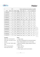
˙L 1, ˙L 2, ˙L 3
 |
View all Haier AV16NMVERA manuals
Add to My Manuals
Save this manual to your list of manuals |
Page 104 highlights
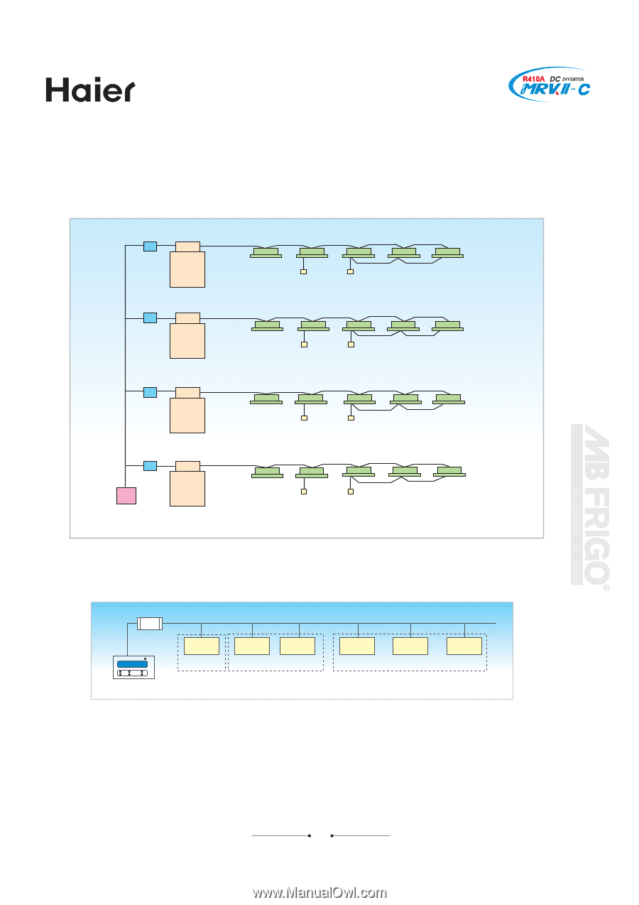
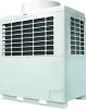
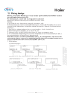
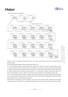
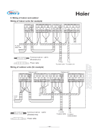
Note: 1. In the above figure, the state in the frame is set when out of factory. 2. The indoor controlled by master/slave wired controller and the indoor controlled by individual wired controller are all wired controlled master indoor. 3. The remote receiver is equipped with a multi-wire which can be inserted in CN21. 4. Central control system connecting board iGU04 outdoor (master unit) indoor unit Unit No. 1 iGU04 outdoor (master unit) indoor unit Unit No. 4 iGU04 outdoor (master unit) indoor unit Unit No. 7 iGU04 outdoor (master unit) indoor unit Unit No. 62 Central controller (64 units) Unit No. 2 Wired controller Unit (group control, 1:16) No. 3 Unit No. 5 Unit No. 6 Unit No. 8 Unit No. 9 Unit No. 63 Unit No. 64 Can set the central control unit as a group, and the max. 64 units of indoor can be set a group. After setting unit, the indoor in one group can be controlled the same operation (when out of factory, one unit is regarded as one group). connecting board IGU04 central controller unit 1 ˙ł 1 unit 2 unit 3 ˙ł 2 unit 1 unit 2 ˙ł 3 unit 3 Figure 2 Central unit and group diagram When the central controller connects one outdoor unit, the connecting board IGU04 is unnecessary. G R U P A d.o.o. 104
-
 1
1 -
2
-
3
-
4
-
5
-
6
-
7
-
8
-
9
-
10
-
11
-
12
-
13
-
14
-
15
-
16
-
17
-
18
-
19
-
20
-
21
-
22
-
23
-
24
-
25
-
26
-
27
-
28
-
29
-
30
-
31
-
32
-
33
-
34
-
35
-
36
-
37
-
38
-
39
-
40
-
41
-
42
-
43
-
44
-
45
-
46
-
47
-
48
-
49
-
50
-
51
-
52
-
53
-
54
-
55
-
56
-
57
-
58
-
59
-
60
-
61
-
62
-
63
-
64
-
65
-
66
-
67
-
68
-
69
-
70
-
71
-
72
-
73
-
74
-
75
-
76
-
77
-
78
-
79
-
80
-
81
-
82
-
83
-
84
-
85
-
86
-
87
-
88
-
89
-
90
-
91
-
92
-
93
-
94
-
95
-
96
-
97
-
98
-
 99
99 -
 100
100 -
 101
101 -
 102
102 -
 103
103 -
 104
104 -
 105
105 -
 106
106 -
 107
107 -
 108
108 -
 109
109 -
110
-
111
-
112
-
113
-
114
-
115
-
116
-
117
-
118
-
119
-
120
-
121
-
122
-
123
-
124
-
125
-
126
-
127
-
128
-
129
 |
 |