Haier AV16NMVERA Design Manual - Page 113
PCB of master unit
 |
View all Haier AV16NMVERA manuals
Add to My Manuals
Save this manual to your list of manuals |
Page 113 highlights
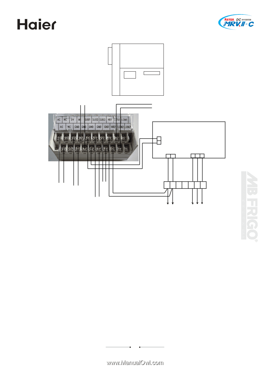
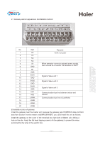
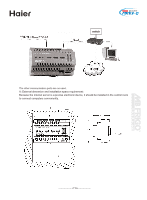
MRV II Commercial Air Conditioning C. Wiring connection of gateway: Gateway Electrical box of Master unit G R U P A d.o.o. To pulse ammeter To other gateway and server PCB of master unit CN44 CN19 CN36 when there is no proper power when there is no To CN44 of slave unit 1 communication terminal block P QX Y A B C supply from 5V signal from PCB, connect it to external pulse ammeter, use the port. To CN44 of slave unit 2 power: 13.8VAC 200mA. To indoor unit To outdoor slave unit Remarks: 1) Power: The power of gateway is AC12V and could be getted from port A and B on the communication terminal block of outdoor master unit and slave unit. There cannt be any error when connecting, or the gateway will be burnt off. 2) LON/LON(LONWORKS communication) connector: connect with the gateway of other master unit and LONWORKS communication connector of internet server, no polarity requirement. 3) HBS/earth wire(serial signal of master unit) wiring: connect with the output port of serial signal (CN35 ) of the master uint PCB, get the parameter of slave unit from serial signal, could not detect slave unit data when in reverse connection. Polarity is required. When using communication wire 0010450044, black wire is connected to the HBS terminal of gateway, and white wire is connected to the earth wire on the right of HBS. 4) Count/ earth wire(pulse signal) wiring: connect pulse ammeter to get the power consumption recorded in the ammeter. Polarity is required. Connect the earth wire terminal of pulse output of ammeter to the earth wire terminal on the right of count terminal of gateway, and the other terminal of pulse output of ammeter connects to the count terminal of gateway. HBM/HBM (HOMEBUS communication) port: connect ports P&Q of the communication terminal block of outdoor master unit and indoor unit, no polarity requirement.. 113
-
 1
1 -
2
-
3
-
4
-
5
-
6
-
7
-
8
-
9
-
10
-
11
-
12
-
13
-
14
-
15
-
16
-
17
-
18
-
19
-
20
-
21
-
22
-
23
-
24
-
25
-
26
-
27
-
28
-
29
-
30
-
31
-
32
-
33
-
34
-
35
-
36
-
37
-
38
-
39
-
40
-
41
-
42
-
43
-
44
-
45
-
46
-
47
-
48
-
49
-
50
-
51
-
52
-
53
-
54
-
55
-
56
-
57
-
58
-
59
-
60
-
61
-
62
-
63
-
64
-
65
-
66
-
67
-
68
-
69
-
70
-
71
-
72
-
73
-
74
-
75
-
76
-
77
-
78
-
79
-
80
-
81
-
82
-
83
-
84
-
85
-
86
-
87
-
88
-
89
-
90
-
91
-
92
-
93
-
94
-
95
-
96
-
97
-
98
-
99
-
100
-
101
-
102
-
103
-
104
-
105
-
106
-
107
-
 108
108 -
 109
109 -
 110
110 -
 111
111 -
 112
112 -
 113
113 -
 114
114 -
 115
115 -
 116
116 -
 117
117 -
 118
118 -
119
-
120
-
121
-
122
-
123
-
124
-
125
-
126
-
127
-
128
-
129
 |
 |