Harman Kardon AVR 354 Owners Manual - Page 11
The Bridge II - reset
 |
View all Harman Kardon AVR 354 manuals
Add to My Manuals
Save this manual to your list of manuals |
Page 11 highlights
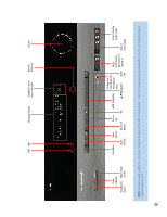
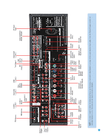
FM Antenna S-Video 1, 2 and 3 Composite 1, 2 and 3 HDMI 1, 2 and 3 AM Antenna S-Video 2 Output Video Monitor Outputs Composite 2 Output Component The Bridge II 1, 2 and 3 HDMI XM Monitor Antenna Output AC Power Input Component Video Monitor Outputs Analog 2 Outputs Zone 2 Audio Outputs Remote Preamp IR Input Outputs Analog 4 Front Speaker Outputs Outputs Remote IR Output 6-/8Channel Inputs Coaxial Digital Audio Output Coaxial 1 and 2 Digital Audio Switched AC Accessory Outlet RS-232 Reset RS-232 Mode Analog 1-5 Carrier Subwoofer Zone 2 Inputs IR Output Output IR Input Surround Back/Zone 2 Speaker Outputs Surround Center Speaker Speaker Outputs Outputs Optical 1, 2 and 3 RS-232 Digital Audio Serial Port NOTE: To make it easier to follow the instructions throughout the manual that refer to this illustration, a copy of this page may be downloaded from the Product Support section at www.harmankardon.com. All connectors are inputs except as indicated. 11
-
 1
1 -
2
-
3
-
4
-
5
-
 6
6 -
 7
7 -
 8
8 -
 9
9 -
 10
10 -
 11
11 -
 12
12 -
 13
13 -
 14
14 -
 15
15 -
 16
16 -
17
-
18
-
19
-
20
-
21
-
22
-
23
-
24
-
25
-
26
-
27
-
28
-
29
-
30
-
31
-
32
-
33
-
34
-
35
-
36
-
37
-
38
-
39
-
40
-
41
-
42
-
43
-
44
-
45
-
46
-
47
-
48
-
49
-
50
-
51
-
52
-
53
-
54
-
55
-
56
-
57
-
58
-
59
-
60
-
61
-
62
-
63
-
64
-
65
-
66
-
67
-
68
-
69
-
70
-
71
-
72
-
73
-
74
-
75
-
76
 |
 |
