Harman Kardon AVR 354 Owners Manual - Page 29
Step Five - Connect the Video Display
 |
View all Harman Kardon AVR 354 manuals
Add to My Manuals
Save this manual to your list of manuals |
Page 29 highlights
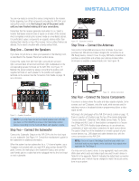
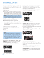
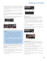
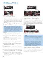
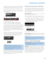
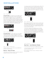
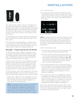
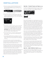
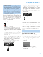
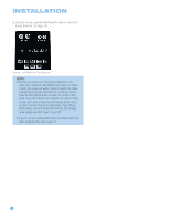
INSTALLATION To make analog audio recordings, connect the recorder's left and right analog audio outputs to the Analog 2 Audio Inputs on the AVR, and the recorder's analog audio inputs to the AVR's Analog 2 Audio Outputs. No video connection is required, although the AVR will display any signal at the video input assigned to the same source as the Analog 2 Audio Inputs. See Figure 29. Connecting a Game Console, Camera or Other Device If a device will only be connected temporarily, you may use the audio/ video inputs on the front panel. When not in use, place the supplied covers over the jacks for a cleaner appearance by snapping the covers in place. To remove the covers, gently press on the left side of each cover so that it pivots out. AVR 354 Figure 29 - Connecting an Audio Recorder Connect an iPod Using Docking Station Video Components: Install video components, e.g., game consoles and camcorders, as follows (see Figure 31): • Connect the component's S-video or composite video output (use only one connection) to the corresponding front-panel Input on the AVR. • Connect the component's optical or coaxial digital audio output to either the Optical or Coaxial Input on the front panel (if available). For fully analog devices, connect the device's analog audio outputs to the AVR's front-panel Analog Audio Inputs. The AVR 354 includes The Bridge II, a docking station compatible with most docking iPod models, 4G and later (not included). Enjoy audio and video content stored on the iPod, with all the power and fidelity of your home theater system. With The Bridge II, navigation and control of the iPod is a simple matter of using the preprogrammed AVR remote and following the on-screen menus. The system even charges the iPod when the AVR is powered on. Simply plug the proprietary cable from The Bridge II into the special The Bridge II connector on the rear of the AVR 354. See Figure 30. Use the dock adapter supplied with the iPod, or obtain an adapter to avoid damaging The Bridge II or the Apple iPod during use. AVR 354 Figure 31 - Connecting a Device to the Front-Panel Inputs Audio Components: Connect audio-only devices, such as CD players, to either the Coaxial or Optical Digital Audio Inputs, or the Analog Audio Inputs (see Figure 31). AVR 354 NOTE: If your video devices are equipped with HDMI or component video outputs, you may connect them to any available audio and video input on the AVR. Step Five - Connect the Video Display Figure 30 - The Bridge II Connector NOTE: The original version of this accessory, known as The Bridge, is not compatible with the AVR 354. Should you misplace The Bridge II that is included with the AVR 354 in the future, contact Harman Kardon and make sure to order The Bridge II as a replacement. Alternatively, or if you have another brand of portable audio player, use an interconnect with a stereo 1/8-inch mini-plug at one end and two RCA plugs at the other end to connect the player to the Audio Inputs on the AVR's front panel. See Figure 31. IMPORTANT NOTE: Do not connect any video output on the video display (TV) to any video input on the AVR. Doing so will cause undesirable video interference. HDMI Video: If the display has an HDMI input, connect the HDMI Monitor Output to the display (see Figure 32). Thanks to the AVR 354's sophisticated video processing and upscaling capabilities, no other video connections are required from the AVR to the video display. Analog video sources (composite, S-video and component) are converted to the HDMI format and upscaled to as much as 1080p resolution, depending on the display's capabilities. Proceed to Step Six. 29
-
 1
1 -
2
-
3
-
4
-
5
-
6
-
7
-
8
-
9
-
10
-
11
-
12
-
13
-
14
-
15
-
16
-
17
-
18
-
19
-
20
-
21
-
22
-
23
-
 24
24 -
 25
25 -
 26
26 -
 27
27 -
 28
28 -
 29
29 -
 30
30 -
 31
31 -
 32
32 -
 33
33 -
 34
34 -
35
-
36
-
37
-
38
-
39
-
40
-
41
-
42
-
43
-
44
-
45
-
46
-
47
-
48
-
49
-
50
-
51
-
52
-
53
-
54
-
55
-
56
-
57
-
58
-
59
-
60
-
61
-
62
-
63
-
64
-
65
-
66
-
67
-
68
-
69
-
70
-
71
-
72
-
73
-
74
-
75
-
76
 |
 |
