Harman Kardon AVR 354 Owners Manual - Page 21
Antennas - upgrade
 |
View all Harman Kardon AVR 354 manuals
Add to My Manuals
Save this manual to your list of manuals |
Page 21 highlights
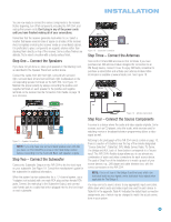
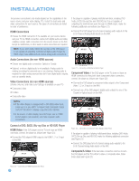
CONNECTIONS required for DVD-Audio players compliant with HDMI version 1.1 or better, or HD-DVD and Blu-ray Disc players that decode the digital audio internally and output linear PCM signals in digital format. Consult the owner's guide for your disc player for more information. Multichannel analog audio cable (RCA) Front Surround Center Subwoofer Figure 8 - Multichannel Analog Audio Harman Kardon receivers also include a proprietary, dedicated audio connection called The Bridge II. If you own a docking iPod (most models, 4G or later), connect The Bridge II (included) to The Bridge II port on the receiver. See Figure 9. Dock your iPod (not included) in The Bridge II, and you may listen to your audio materials through your high-performance audio system. You may view still images or video materials stored on a photo- or video-capable iPod that supports video browsing. You may even use the AVR 354 remote to control the iPod with navigation messages displayed on the front panel and on a video display connected to the AVR. The Bridge II outputs analog audio to the AVR 354, and it is available to the multiroom system. Figure 9 - The Bridge II Video Connections Although some sources only produce an audio signal (e.g., CD player, tape deck), many sources output both audio and video signals (e.g., DVD player, cable television box, HDTV tuner, satellite box, VCR, DVR). In addition to the audio connection, make one type of video connection for each of these sources (only one at a time for any source). Digital Video If you have already connected a source device to one of the HDMI inputs as explained in the Digital Audio Connections section, you have automatically made a video connection at the same time, as the HDMI signal includes both digital audio and video components. If the source device is not capable of transmitting its digital audio signal through the HDMI connection, use one of the coaxial or optical digital audio inputs for the source. If a multichannel analog audio connection is required for certain lossless formats (e.g., DVD-Audio, SACD, Blu-ray Disc or HD-DVD), you may make both audio connections. To listen to the multichannel disc, change the Audio Input From Source setting in the Info Settings menu to "6/8 Channel." Analog Video There are three types of analog video connections: composite video, S-video and component video. Composite video is the basic connection most commonly available. The jack is usually color-coded yellow, and looks like an analog audio jack, although it is important never to confuse the two. Do not plug a composite video cable into an analog or coaxial digital audio jack, or vice versa. Both the chrominance (color) and luminance (intensity) components of the video signal are transmitted using a single cable. See Figure 10. Composite video cable Figure 10 - Composite Video S-video, or "separate" video, transmits the chrominance and luminance components using separate wires contained within a single cable. The plug on an S-video cable contains four metal pins, plus a plastic guide pin. Be careful to line up the plug correctly when you insert it into the jack on the receiver, source or video display. See Figure 11. S-video cable Figure 11 - S-Video Component video separates the video signal into three components - one luminance ("Y") and two sub-sampled color signals ("Pb" and "Pr") - that are transmitted using three separate cables. The "Y" cable is colorcoded green, the "Pb" cable is colored blue and the "Pr" cable is colored red. See Figure 12. Component video cable Figure 12 - Component Video If it's available on your video display, an HDMI connection is recommended as the best quality connection, followed by component video, S-video and then composite video. NOTES: • Copy-protected sources are not available at the Component Video Monitor Outputs. • Standard and high-definition analog video signals are upscaled to 1080i resolution for the Component Video Monitor Outputs. For improved video performance, consider upgrading to an HDMI-capable video display with 1080p resolution. Antennas The AVR 354 uses separate terminals for the included FM and AM antennas that provide proper reception for the tuner. 21 21
-
 1
1 -
2
-
3
-
4
-
5
-
6
-
7
-
8
-
9
-
10
-
11
-
12
-
13
-
14
-
15
-
 16
16 -
 17
17 -
 18
18 -
 19
19 -
 20
20 -
 21
21 -
 22
22 -
 23
23 -
 24
24 -
 25
25 -
 26
26 -
27
-
28
-
29
-
30
-
31
-
32
-
33
-
34
-
35
-
36
-
37
-
38
-
39
-
40
-
41
-
42
-
43
-
44
-
45
-
46
-
47
-
48
-
49
-
50
-
51
-
52
-
53
-
54
-
55
-
56
-
57
-
58
-
59
-
60
-
61
-
62
-
63
-
64
-
65
-
66
-
67
-
68
-
69
-
70
-
71
-
72
-
73
-
74
-
75
-
76
 |
 |
