HP 12000 HP StorageWorks 12000 Gateway Virtual Library System User Guide (AH81 - Page 99
Operation, Powering on the VLS12000 System
 |
View all HP 12000 manuals
Add to My Manuals
Save this manual to your list of manuals |
Page 99 highlights
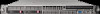
7 Operation This section describes how to power on and power off the nodes. Powering on the VLS12000 System 1. Power on all arrays connected to the VLS. 2. Power on the two private LAN switches connected to the VLS. 3. Plug the VLS nodes' AC power cords into a power source if not already connected. 4. Press the VLS secondary nodes' Power On/Standby button. After the secondary nodes are powering up, press the primary node's Power On/Standby button. 5. Confirm that the VLS components are all functioning normally and the VLS is cabled correctly by observing the condition of their status LEDs. The LED status should match those shown in the following table. If an LED status does not match the status shown in the following table, a component needs attention. Figure 15 VLS12000 node LED status during normal operation . Item 1 2 3 4 5 Description Internal health LED External health LED (power supply) NIC 1 link LED NIC 2 link LED Power supply LEDs Status LED is green. LED is green. LED is green if primary node. LED is off if secondary node. LED is green. LED is green. HP StorageWorks 12000 Gateway Virtual Library System User Guide 99
-
 1
1 -
2
-
3
-
4
-
5
-
6
-
7
-
8
-
9
-
10
-
11
-
12
-
13
-
14
-
15
-
16
-
17
-
18
-
19
-
20
-
21
-
22
-
23
-
24
-
25
-
26
-
27
-
28
-
29
-
30
-
31
-
32
-
33
-
34
-
35
-
36
-
37
-
38
-
39
-
40
-
41
-
42
-
43
-
44
-
45
-
46
-
47
-
48
-
49
-
50
-
51
-
52
-
53
-
54
-
55
-
56
-
57
-
58
-
59
-
60
-
61
-
62
-
63
-
64
-
65
-
66
-
67
-
68
-
69
-
70
-
71
-
72
-
73
-
74
-
75
-
76
-
77
-
78
-
79
-
80
-
81
-
82
-
83
-
84
-
85
-
86
-
87
-
88
-
89
-
90
-
91
-
92
-
93
-
 94
94 -
 95
95 -
 96
96 -
 97
97 -
 98
98 -
 99
99 -
 100
100 -
 101
101 -
 102
102 -
 103
103 -
 104
104 -
105
-
106
-
107
-
108
-
109
-
110
-
111
-
112
-
113
-
114
-
115
-
116
-
117
-
118
-
119
-
120
-
121
-
122
-
123
-
124
-
125
-
126
-
127
-
128
-
129
-
130
-
131
-
132
-
133
-
134
-
135
-
136
-
137
-
138
-
139
-
140
-
141
-
142
-
143
-
144
-
145
-
146
-
147
-
148
-
149
-
150
-
151
-
152
-
153
-
154
-
155
-
156
-
157
-
158
-
159
-
160
-
161
-
162
-
163
-
164
-
165
-
166
-
167
-
168
-
169
-
170
-
171
-
172
-
173
-
174
-
175
-
176
-
177
-
178
-
179
-
180
-
181
-
182
-
183
-
184
-
185
-
186
-
187
-
188
-
189
-
190
-
191
-
192
-
193
-
194
-
195
-
196
-
197
-
198
-
199
-
200
-
201
-
202
-
203
-
204
-
205
-
206
-
207
-
208
-
209
-
210
-
211
-
212
-
213
-
214
-
215
-
216
-
217
-
218
-
219
-
220
-
221
-
222
-
223
-
224
-
225
-
226
-
227
-
228
-
229
-
230
-
231
-
232
-
233
-
234
-
235
-
236
-
237
-
238
-
239
-
240
-
241
-
242
-
243
-
244
-
245
-
246
-
247
-
248
-
249
-
250
-
251
-
252
-
253
-
254
-
255
-
256
-
257
-
258
-
259
-
260
-
261
-
262
-
263
-
264
 |
 |
