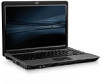
HP 540 HP 540 Notebook PC and HP 541 Notebook PC - Maintenance and Service Gui
HP 540 - Notebook PC Manual
 |
View all HP 540 manuals
Add to My Manuals
Save this manual to your list of manuals |
HP 540 manual content summary:
- HP 540 | HP 540 Notebook PC and HP 541 Notebook PC - Maintenance and Service Gui - Page 1
HP 540 Notebook PC HP 541 Notebook PC Maintenance and Service Guide - HP 540 | HP 540 Notebook PC and HP 541 Notebook PC - Maintenance and Service Gui - Page 2
Copyright 2008 Hewlett-Packard Development Company, L.P. Bluetooth is a trademark owned by its proprietor HP products and services are set forth in the express warranty statements accompanying such products and services. Nothing herein should be construed as constituting an additional warranty. HP - HP 540 | HP 540 Notebook PC and HP 541 Notebook PC - Maintenance and Service Gui - Page 3
MSG revision history Revision A Publication date January 2010 Description The 14.1-inch WXGA BrightView display assembly for use with the HP 541 model, part number 517616-001, has been added in the following locations: Product description on page 1, Computer major components on page 15, - HP 540 | HP 540 Notebook PC and HP 541 Notebook PC - Maintenance and Service Gui - Page 4
iv MSG revision history - HP 540 | HP 540 Notebook PC and HP 541 Notebook PC - Maintenance and Service Gui - Page 5
Safety warning notice WARNING! To reduce the possibility of heat-related injuries or of overheating the computer, do not place the computer directly on your lap or obstruct the computer air vents. Use the computer only on a hard, flat surface. Do not allow another hard surface, such as an adjoining - HP 540 | HP 540 Notebook PC and HP 541 Notebook PC - Maintenance and Service Gui - Page 6
vi Safety warning notice - HP 540 | HP 540 Notebook PC and HP 541 Notebook PC - Maintenance and Service Gui - Page 7
Right-side components ...10 Left-side components ...11 Bottom components ...12 Wireless antennae (select models only 13 3 Illustrated parts catalog Serial number procedures Preliminary replacement requirements 29 Tools required ...29 Service considerations ...29 Plastic parts ...29 Cables and - HP 540 | HP 540 Notebook PC and HP 541 Notebook PC - Maintenance and Service Gui - Page 8
board 61 Bluetooth module ...64 System board ...66 Fan ...69 Heat sink ...71 Processor ...74 Modem module ...76 RTC battery ...78 ExpressCard Configuration menu 85 6 Specifications Computer specifications ...88 14.1-inch, WXGA display specifications 89 Hard drive specifications ...90 DVD±RW and - HP 540 | HP 540 Notebook PC and HP 541 Notebook PC - Maintenance and Service Gui - Page 9
System interrupt specifications ...94 System I/O address specifications ...95 System memory map specifications 97 7 Screw listing Phillips PM2 the operating system and programs 123 9 Connector pin assignments Audio-out (headphone) ...124 Audio-in (microphone) ...124 External monitor ...125 RJ-11 - HP 540 | HP 540 Notebook PC and HP 541 Notebook PC - Maintenance and Service Gui - Page 10
10 Power cord set requirements Requirements for all countries and regions 128 Requirements for specific countries and regions 129 11 Recycling Battery ...130 Display ...130 Index ...136 x - HP 540 | HP 540 Notebook PC and HP 541 Notebook PC - Maintenance and Service Gui - Page 11
Computer models equipped with GLE960 system board HP 540 Computer models equipped with GME965 system board HP 540 Computer models equipped with PM965 system board HP 541 Product Name HP 540 Notebook PC √ √ √ Processors Chipset HP 541 Notebook PC Intel® Core™2 Duo processors ● T5670 1.80-GHz - HP 540 | HP 540 Notebook PC and HP 541 Notebook PC - Maintenance and Service Gui - Page 12
assemblies include 2 wireless √ local area network (WLAN) antennae ● 14.1-inch WXGA BrightView √ ● 14.1-inch WXGA BrightView 2 customer-accessible/upgradable √ memory module slots Supports dual-channel memory √ Supports up to 4 GB of system RAM √ √ √ √ √ √ √ √ √ √ √ √ √ PC2 - HP 540 | HP 540 Notebook PC and HP 541 Notebook PC - Maintenance and Service Gui - Page 13
drives Diskette drive Description Computer models equipped with GLE960 system board HP 540 Computer models equipped with GME965 system board HP 540 Computer models equipped with PM965 system board HP 541 Supports the following configurations only √ in Brazil: ● 2048-MB total system memory - HP 540 | HP 540 Notebook PC and HP 541 Notebook PC - Maintenance and Service Gui - Page 14
with PM965 system board HP 541 Audio Modem Ethernet HD audio - ADI1981 √ 56K Vulcan-F 1.5-inch data/fax modem √ with digital line guard Intel 82562GT √ S3/S4/S5 wake on LAN: DC - no √ S3/S4/S5 wake on LAN: AC - yes √ √ √ √ √ √ √ √ √ √ √ Wireless Integrated WLAN options by - HP 540 | HP 540 Notebook PC and HP 541 Notebook PC - Maintenance and Service Gui - Page 15
Computer models equipped with PM965 system board HP 541 √ √ √ √ √ √ √ √ √ TouchPad only, with 2 TouchPad buttons √ and vertical scrolling (taps enabled as default) 90-W AC adapter with localized cable plug support (2-wire plug with ground pin, supports 2-pin DC connector) 65-W AC adapter - HP 540 | HP 540 Notebook PC and HP 541 Notebook PC - Maintenance and Service Gui - Page 16
Category Serviceability Description Computer models equipped with GLE960 system board HP 540 Computer models equipped with GME965 system board HP 540 Computer models equipped with PM965 system board HP 541 Windows Vista Business with XP √ Professional (in Japan only) Windows Vista Business - HP 540 | HP 540 Notebook PC and HP 541 Notebook PC - Maintenance and Service Gui - Page 17
up or down. *This table describes factory settings. View or change pointing device preferences as follows: ● In Windows Vista, select Start > Control Panel > Hardware and Sound > Mouse. ● In Windows XP, select Start > Control Panel > Printers and Other Hardware > Mouse. Top components 7 - HP 540 | HP 540 Notebook PC and HP 541 Notebook PC - Maintenance and Service Gui - Page 18
You must set up or access a wireless network to establish a wireless connection. ● Blue: An integrated wireless device, such as a wireless local area network (WLAN) device, the HP Broadband Wireless Module, and/or a Bluetooth® device, is on. ● Amber: All wireless devices are off. ● When the computer - HP 540 | HP 540 Notebook PC and HP 541 Notebook PC - Maintenance and Service Gui - Page 19
is in the Sleep state (Windows Vista) or Standby (Windows XP). ● Off: The computer is off or in Hibernation. Produces sound. Item (1) Component esc key (2) fn key (3) Windows logo key (4) Windows applications key (5) Embedded numeric keypad keys (6) Function keys Function Displays - HP 540 | HP 540 Notebook PC and HP 541 Notebook PC - Maintenance and Service Gui - Page 20
Function Connects optional powered stereo speakers, headphones, ear buds, a headset, or television audio. Connects an optional computer headset microphone, stereo array microphone, or monaural microphone. Supports the following optional digital card formats: ● Secure Digital (SD) Memory Card - HP 540 | HP 540 Notebook PC and HP 541 Notebook PC - Maintenance and Service Gui - Page 21
or projector. Connects an AC adapter. Connects a network cable. Connect optional USB devices. Supports optional ExpressCards. ● Amber: A battery is charging. ● Turquoise: A battery is close to full charge capacity. ● Blinking amber: A battery that is the only available power source has reached a low - HP 540 | HP 540 Notebook PC and HP 541 Notebook PC - Maintenance and Service Gui - Page 22
Release the battery from the battery bay. Holds the battery. Enable airflow wireless devices in your country or region. If you replace the module and then receive a warning message, remove the module to restore computer functionality, and then contact technical support through Help and Support - HP 540 | HP 540 Notebook PC and HP 541 Notebook PC - Maintenance and Service Gui - Page 23
at least 2 antennae send and receive signals from one or more wireless devices. These antennae are not visible from the outside of the computer keep the areas immediately around the antennae free from obstructions. To see wireless regulatory notices, refer to the section of the Regulatory, Safety and - HP 540 | HP 540 Notebook PC and HP 541 Notebook PC - Maintenance and Service Gui - Page 24
This number provides specific information about the product's hardware components. The part number helps a service technician to determine what components and parts are needed. ● Model Description (4). This is the number you use to locate documents, drivers, and support for your notebook. ● Warranty - HP 540 | HP 540 Notebook PC and HP 541 Notebook PC - Maintenance and Service Gui - Page 25
Computer major components Computer major components 15 - HP 540 | HP 540 Notebook PC and HP 541 Notebook PC - Maintenance and Service Gui - Page 26
2 WLAN antenna transceivers and cables) 14.1-inch, WXGA BrightView display assembly for use with HP 540 models 500004-001 14.1-inch, WXGA BrightView display assembly for use with HP 541 models 517616-001 Display internal components: Display bezel 500000-001 Display enclosure (includes 2 WLAN - HP 540 | HP 540 Notebook PC and HP 541 Notebook PC - Maintenance and Service Gui - Page 27
73-GHz (1-MB L2 cache, 533-MHz FSB) 506448-001 RTC battery 449137-001 Broadcom Bluetooth modules (do not include Bluetooth module cable) NOTE: The Bluetooth module spare part kits do not include a Bluetooth module cable. The Bluetooth module cable is included in the Cable Kit, spare part number - HP 540 | HP 540 Notebook PC and HP 541 Notebook PC - Maintenance and Service Gui - Page 28
Item (18) (19) (20) Description Spare part number Cable Kit (not illustrated; see Cable Kit on page 20 for more Cable Kit spare part number information) 457400-001 WLAN modules Intel 802.11 a/b/g/n WLAN modules: ● For use in Antigua and Barbuda, Argentina, Aruba, the Bahamas, Barbados, Bermuda - HP 540 | HP 540 Notebook PC and HP 541 Notebook PC - Maintenance and Service Gui - Page 29
Plastics Kit Item Description Plastics Kit: (1) Hard drive bay cover (includes 2 captive screws, secured by C-clips) (2) WLAN module compartment cover (includes one captive screw, secured by a C-clip) (3) ExpressCard slot protective insert (4) Memory module compartment cover (includes one captive - HP 540 | HP 540 Notebook PC and HP 541 Notebook PC - Maintenance and Service Gui - Page 30
Cable Kit Item Description Cable Kit: (1) RJ-11 jack cable (2) Display lid switch module and cable (3) Bluetooth module cable Spare part number 457400-001 20 Chapter 3 Illustrated parts catalog - HP 540 | HP 540 Notebook PC and HP 541 Notebook PC - Maintenance and Service Gui - Page 31
-RW Combo Drive (PATA) DVD-ROM Drive (PATA) DVD±RW and CD-RW Super Multi Double-Layer Combo Drive with LightScribe (SATA) DVD CD-RW Combo Drive (SATA) DVD-ROM Drive (SATA) (2) Hard drives (include bracket) 250-GB, 5400-rpm 160-GB, 5400-rpm 120-GB, 5400-rpm Spare part number 500018-001 - HP 540 | HP 540 Notebook PC and HP 541 Notebook PC - Maintenance and Service Gui - Page 32
Miscellaneous parts Description Spare part number AC adapters 65-W AC adapter (for use only with computer models with UMA graphics system memory) 417220-001 90-W slim AC adapter (for use only with computer models with discrete graphics system memory) 374791-001 for use in Asia and China. Logo - HP 540 | HP 540 Notebook PC and HP 541 Notebook PC - Maintenance and Service Gui - Page 33
Description For use in Korea Screw Kit ● Phillips PM3.0×4.0 screw ● Phillips PM2.5×12.0 captive screw ● Phillips PM2.5×10.0 captive screw ● Phillips PM2.5×7.0 captive screw ● Phillips PM2.5×7.0 screw ● Phillips PM2.5×4.0 screw ● Phillips PM2.0×8.0 screw ● Phillips PM2.0×6.0 screw ● Phillips PM2 - HP 540 | HP 540 Notebook PC and HP 541 Notebook PC - Maintenance and Service Gui - Page 34
Korea Intel 802.11 a/b/g/n WLAN module for use in Japan RTC battery Bluetooth module for use in Japan and Asia Pacific countries and regions NOTE: The Bluetooth module spare part kits do not include a Bluetooth module cable. The Bluetooth module cable is included in the Cable Kit, spare part number - HP 540 | HP 540 Notebook PC and HP 541 Notebook PC - Maintenance and Service Gui - Page 35
Spare part number 451861-002 451861-003 451861-291 456576-AD1 456593-001 456605-001 456606-001 456614-001 456618-001 456619-001 457400-001 459263-001 459263-002 460702-001 461749-001 Description Intel 802.11 a/b/g WLAN module for use in Austria, Azerbaijan, Bahrain, Belgium, Brazil, Bulgaria, - HP 540 | HP 540 Notebook PC and HP 541 Notebook PC - Maintenance and Service Gui - Page 36
490371-D01 Power cord for use in Argentina 490371-D611 Power cord for use in India 495386-001 495387-001 DVD-ROM Drive (SATA) 495395-001 System board for use only with computer models equipped with Intel Celeron M processors and UMA graphics subsystem (includes replacement thermal material - HP 540 | HP 540 Notebook PC and HP 541 Notebook PC - Maintenance and Service Gui - Page 37
enclosure (includes 2 wireless antenna transceivers and cables display assembly for use with HP 540 models (includes 2 (includes bracket) 6-cell, 47-Wh Li-ion battery DVD-ROM Drive (includes bezel and bracket) bracket) (SATA) DVD/CD-RW Combo Drive (includes bezel and bracket) (SATA) Intel Celeron - HP 540 | HP 540 Notebook PC and HP 541 Notebook PC - Maintenance and Service Gui - Page 38
discrete memory subsystem LCD Cable Kit (for use only with computer models with discrete graphics system memory) 14.1-inch, WXGA display assembly for use with HP 541 models (includes 2 WLAN antenna transceivers and cables) 28 Chapter 3 Illustrated parts catalog - HP 540 | HP 540 Notebook PC and HP 541 Notebook PC - Maintenance and Service Gui - Page 39
● Magnetic screwdriver ● Phillips P0 and P1 screwdrivers ● Torx T8 screwdriver Service considerations The following sections include some of the considerations that you must keep in Apply pressure only at the points designated in the maintenance instructions. Preliminary replacement requirements 29 - HP 540 | HP 540 Notebook PC and HP 541 Notebook PC - Maintenance and Service Gui - Page 40
Cables and connectors CAUTION: When servicing the computer, be sure that cables are placed in their proper locations during the reassembly process. Improper cable placement can damage the computer. Cables must - HP 540 | HP 540 Notebook PC and HP 541 Notebook PC - Maintenance and Service Gui - Page 41
Grounding guidelines Electrostatic discharge damage Electronic components are sensitive to electrostatic discharge (ESD). Circuitry design and structure determine the degree of sensitivity. Networks built into many integrated circuits provide some protection, but in many cases, ESD contains enough - HP 540 | HP 540 Notebook PC and HP 541 Notebook PC - Maintenance and Service Gui - Page 42
material. ● Use a wrist strap connected to a properly grounded work surface and use properly grounded tools and equipment. ● Use conductive field service tools, such as cutters, screwdrivers, and vacuums. ● When fixtures must directly contact dissipative surfaces, use fixtures made only of static - HP 540 | HP 540 Notebook PC and HP 541 Notebook PC - Maintenance and Service Gui - Page 43
with ground cords of one megohm resistance ● Static-dissipative tables or floor mats with hard ties to the ground ● Field service kits ● Static awareness labels ● Material-handling packages ● Nonconductive plastic bags, tubes, or boxes ● Metal tote boxes ● Electrostatic voltage levels and - HP 540 | HP 540 Notebook PC and HP 541 Notebook PC - Maintenance and Service Gui - Page 44
Unknown user password If the computer you are servicing has an unknown user password, follow these steps Remove the battery (see Battery on page 37). 5. Remove the real-time clock (RTC) battery (see RTC battery on page 78). 6. Wait approximately 5 minutes. 7. Replace the RTC battery and reassemble - HP 540 | HP 540 Notebook PC and HP 541 Notebook PC - Maintenance and Service Gui - Page 45
number to HP when requesting specific information about the product's hardware components. The part number helps a service technician to determine what components and parts are needed. ● Model Description (4). This is the number you use to locate documents, drivers, and support for your notebook - HP 540 | HP 540 Notebook PC and HP 541 Notebook PC - Maintenance and Service Gui - Page 46
Computer feet The computer feet are adhesive-backed rubber pads. The feet are included in the Rubber Kit, spare part number 500132-001. There are 4 rubber feet that attach to the base enclosure in the locations illustrated below. 36 Chapter 4 Removal and replacement procedures - HP 540 | HP 540 Notebook PC and HP 541 Notebook PC - Maintenance and Service Gui - Page 47
from the computer. Remove the battery: 1. Turn the computer upside down on a flat surface, with the battery bay toward you. 2. Slide the battery release latches (1) to release the battery. 3. Remove the battery (2) from the computer. Insert the battery into the battery bay until it is seated - HP 540 | HP 540 Notebook PC and HP 541 Notebook PC - Maintenance and Service Gui - Page 48
from the computer by first unplugging the power cord from the AC outlet and then unplugging the AC adapter from the computer. 4. Remove the battery (see Battery on page 37). Remove the hard drive: 1. Position the computer with the front toward you. 2. Loosen the two Phillips PM2.0×5.0 captive screws - HP 540 | HP 540 Notebook PC and HP 541 Notebook PC - Maintenance and Service Gui - Page 49
6. Remove the hard drive (4) from the hard drive bay. 7. If it is necessary to replace the hard drive bracket, remove the two Phillips PM3.0×4.0 hard drive bracket screws (1) from each side of the hard drive. 8. Lift the bracket (2) straight up to remove it from the hard drive. Reverse this - HP 540 | HP 540 Notebook PC and HP 541 Notebook PC - Maintenance and Service Gui - Page 50
WLAN module Description spare part numbers Intel 802.11 a/b/g/n WLAN modules: ● For use in Antigua and Barbuda, Argentina, Aruba, the Bahamas, Barbados, Bermuda, Brunei, 441086-001 Canada, the Cayman Islands, Chile, Colombia, Costa Rica, the Dominican Republic, Ecuador, El Salvador, Guam, - HP 540 | HP 540 Notebook PC and HP 541 Notebook PC - Maintenance and Service Gui - Page 51
Description spare part numbers ● For use in Austria, Azerbaijan, Bahrain, Belgium, Brazil, Bulgaria, Croatia, Cyprus, the Czech 441082-002 Republic, Denmark, Egypt, Estonia, Finland, France, Georgia, Germany, Greece, Hungary, Iceland, Ireland, Israel, Italy, Latvia, Lebanon, Liechtenstein, - HP 540 | HP 540 Notebook PC and HP 541 Notebook PC - Maintenance and Service Gui - Page 52
the computer by first unplugging the power cord from the AC outlet and then unplugging the AC adapter from the computer. 4. Remove the battery (see Battery on page 37). Remove the WLAN module: 1. Position the computer with the front toward you. 2. Loosen the Phillips PM2.0×5.0 captive screw (1) that - HP 540 | HP 540 Notebook PC and HP 541 Notebook PC - Maintenance and Service Gui - Page 53
computer by first unplugging the power cord from the AC outlet and then unplugging the AC adapter from the computer. 4. Remove the battery (see Battery on page 37). Remove the memory module: 1. Loosen the Phillips PM2.0×5.0 captive screw (1) that secures the memory module compartment cover to the - HP 540 | HP 540 Notebook PC and HP 541 Notebook PC - Maintenance and Service Gui - Page 54
2. Lift the front edge of the cover (2), swing it up and back, and remove the cover. The memory module compartment cover is included in the Plastics Kit, spare part number 456614-001. 3. Spread the retaining tabs (1) on each side of the memory module slot to release the memory module. (The edge of - HP 540 | HP 540 Notebook PC and HP 541 Notebook PC - Maintenance and Service Gui - Page 55
RW SuperMulti Double-Layer Combo Drive with LightScribe (SATA DVD/CD-RW Combo Drive (SATA) DVD-ROM Drive (SATA) spare part numbers 500018-001 500017-001 500016 then unplugging the AC adapter from the computer. 4. Remove the battery (see Battery on page 37). Remove the optical drive: 1. Position the - HP 540 | HP 540 Notebook PC and HP 541 Notebook PC - Maintenance and Service Gui - Page 56
5. If it is necessary to replace the optical drive bracket, position the optical drive with the rear toward you. 6. Remove the two Phillips PM2.0×4.0 screws (1) that secure the optical drive bracket to the optical drive. 7. Remove the optical drive bracket (2). Reverse this procedure to reassemble - HP 540 | HP 540 Notebook PC and HP 541 Notebook PC - Maintenance and Service Gui - Page 57
the computer by first unplugging the power cord from the AC outlet and then unplugging the AC adapter from the computer. 4. Remove the battery (see Battery on page 37). Remove the switch cover and keyboard: 1. Remove the following screws: (1) Two slotted Torx ST8M2.5×7.0 screws (2) Two Torx T8M2 - HP 540 | HP 540 Notebook PC and HP 541 Notebook PC - Maintenance and Service Gui - Page 58
2. Remove the two slotted Torx ST8M2.5×7.0 screws that secure the keyboard to the computer. 3. Turn the computer display-side up, with the front toward you. 4. Open the computer as far as possible. 5. Lift the switch cover (1) straight up until it disengages from the computer, and slide it back (2) - HP 540 | HP 540 Notebook PC and HP 541 Notebook PC - Maintenance and Service Gui - Page 59
6. Lift the rear edge of the keyboard (1) until it rests at an angle, and slide it back (2) until it rests on the display assembly and switch cover. 7. Release the zero insertion force (ZIF) connector (1) to which the keyboard cable is attached, and disconnect the keyboard cable (2) from the system - HP 540 | HP 540 Notebook PC and HP 541 Notebook PC - Maintenance and Service Gui - Page 60
9. Release the ZIF connector (1) to which the button board cable is attached, and disconnect the button board cable (2) from the system board. 10. Remove the switch cover. Reverse this procedure to install the switch cover and keyboard. 50 Chapter 4 Removal and replacement procedures - HP 540 | HP 540 Notebook PC and HP 541 Notebook PC - Maintenance and Service Gui - Page 61
from the computer by first unplugging the power cord from the AC outlet and then unplugging the AC adapter from the computer. 4. Remove the battery (see Battery on page 37). 5. Remove the keyboard (see Switch cover and keyboard on page 47). 6. Remove the switch cover (see Switch cover and keyboard - HP 540 | HP 540 Notebook PC and HP 541 Notebook PC - Maintenance and Service Gui - Page 62
from the computer by first unplugging the power cord from the AC outlet and then unplugging the AC adapter from the computer. 4. Remove the battery (see Battery on page 37). 5. Remove the keyboard (see Switch cover and keyboard on page 47). 6. Remove the switch cover (see Switch cover and keyboard - HP 540 | HP 540 Notebook PC and HP 541 Notebook PC - Maintenance and Service Gui - Page 63
assembly for use with HP 540 models 14.1-inch, WXGA BrightView display assembly for use with HP 541 models Spare part number 500004 the AC adapter from the computer. 4. Remove the battery (see Battery on page 37). 5. Disconnect the wireless antenna cables from the WLAN module (see WLAN module - HP 540 | HP 540 Notebook PC and HP 541 Notebook PC - Maintenance and Service Gui - Page 64
display panel cables (1) and (2) from the system board. 6. Remove the wireless antenna cables (3) from the clips and routing channels built into the top cover to the computer. CAUTION: Support the display assembly when removing the following screws. Failure to support the display assembly can result - HP 540 | HP 540 Notebook PC and HP 541 Notebook PC - Maintenance and Service Gui - Page 65
9. If it is necessary to replace the display bezel, display inverter, or display hinges, remove the eight rubber screw covers (1) and the eight Torx T8M2.5×6.0 screws (2) that secure the display bezel to the display assembly. The rubber screw covers are available in the Rubber Kit, spare part number - HP 540 | HP 540 Notebook PC and HP 541 Notebook PC - Maintenance and Service Gui - Page 66
13. Disconnect the display panel cable (2) and the backlight cable (3) from the display inverter. 14. Remove the display inverter. The display inverter is available using spare part number 456618-001. 15. If it is necessary to replace the display hinges, remove the two Torx T8M2.5×6.0 screws (1) - HP 540 | HP 540 Notebook PC and HP 541 Notebook PC - Maintenance and Service Gui - Page 67
18. Remove the display hinges (2). The left and right display hinges are available using spare part number 456619-001. Reverse this procedure to reassemble and install the display assembly. Component replacement procedures 57 - HP 540 | HP 540 Notebook PC and HP 541 Notebook PC - Maintenance and Service Gui - Page 68
from the computer by first unplugging the power cord from the AC outlet and then unplugging the AC adapter from the computer. 4. Remove the battery (see Battery on page 37). 5. Remove the following components: a. Hard drive (see Hard drive on page 38) b. Optical drive (see Optical drive on page 45 - HP 540 | HP 540 Notebook PC and HP 541 Notebook PC - Maintenance and Service Gui - Page 69
2. Remove the followng screws: (1) Three Phillips PM2.0×2.0 broad-head screws (2) Seven slotted Torx ST8M2.5×7.0 screws (3) One Torx T8m2.5×4.0 screw 3. Turn the computer right-side up, with the left side toward you. 4. Press in on the ExpressCard slot eject button (1) two times. The first press - HP 540 | HP 540 Notebook PC and HP 541 Notebook PC - Maintenance and Service Gui - Page 70
10. Release the ZIF connector (4) to which the TouchPad cable is connected and disconnect the TouchPad cable (5) from the system board. 11. Remove the top cover. Reverse this procedure to install the top cover. 60 Chapter 4 Removal and replacement procedures - HP 540 | HP 540 Notebook PC and HP 541 Notebook PC - Maintenance and Service Gui - Page 71
from the computer by first unplugging the power cord from the AC outlet and then unplugging the AC adapter from the computer. 4. Remove the battery (see Battery on page 37). 5. Remove the following components: a. Hard drive (see Hard drive on page 38) b. Optical drive (see Optical drive on page 45 - HP 540 | HP 540 Notebook PC and HP 541 Notebook PC - Maintenance and Service Gui - Page 72
4. Remove the two Phillips PM2.0×4.0 screws (4) that secure the TouchPad bracket to the computer. 5. Release the TouchPad bracket (1) by sliding it back. 6. Remove the TouchPad bracket (2) by lifting it straight up. 7. Remove the TouchPad button board (3). 8. Remove the TouchPad button board cable - HP 540 | HP 540 Notebook PC and HP 541 Notebook PC - Maintenance and Service Gui - Page 73
9. Remove the TouchPad board (1) from the top cover. NOTE: When replacing the TouchPad board and TouchPad button board, be sure the TouchPad button actuators (2) are installed in the top cover. Reverse this procedure to install the TouchPad board and TouchPad button board. Component replacement - HP 540 | HP 540 Notebook PC and HP 541 Notebook PC - Maintenance and Service Gui - Page 74
and regions Spare part number 398393-001 450066-001 Before removing the Bluetooth module, follow these steps: 1. Shut down the computer. If and then unplugging the AC adapter from the computer. 4. Remove the battery (see Battery on page 37). 5. Remove the following components: a. Hard drive ( - HP 540 | HP 540 Notebook PC and HP 541 Notebook PC - Maintenance and Service Gui - Page 75
3. Remove the Bluetooth module (3) from the base enclosure. Reverse this procedure to install the Bluetooth module. Component replacement procedures 65 - HP 540 | HP 540 Notebook PC and HP 541 Notebook PC - Maintenance and Service Gui - Page 76
from the computer by first unplugging the power cord from the AC outlet and then unplugging the AC adapter from the computer. 4. Remove the battery (see Battery on page 37). 5. Remove the following components: a. Hard drive (see Hard drive on page 38) b. Optical drive (see Optical drive on page 45 - HP 540 | HP 540 Notebook PC and HP 541 Notebook PC - Maintenance and Service Gui - Page 77
base enclosure and remove the RJ-11 jack cable from the hook (2) built into the base enclosure. 2. Disconnect the fan cable (3) and the Bluetooth module cable (4) from the system board. 3. Remove the two Phillips PM2.0×6.0 screws (1) and the Torx T8M2.5×4.0 screw (2) that secure the system board to - HP 540 | HP 540 Notebook PC and HP 541 Notebook PC - Maintenance and Service Gui - Page 78
6. Remove the system board (4) from the base enclosure by sliding it back. Reverse the preceding procedure to install the system board. 68 Chapter 4 Removal and replacement procedures - HP 540 | HP 540 Notebook PC and HP 541 Notebook PC - Maintenance and Service Gui - Page 79
from the computer by first unplugging the power cord from the AC outlet and then unplugging the AC adapter from the computer. 4. Remove the battery (see Battery on page 37). 5. Remove the following components: a. Hard drive (see Hard drive on page 38) b. Optical drive (see Optical drive on page 45 - HP 540 | HP 540 Notebook PC and HP 541 Notebook PC - Maintenance and Service Gui - Page 80
high temperature conditions exist. These conditions are affected by high external temperatures, system power consumption, power management/battery conservation configurations, battery fast charging, and software requirements. Exhaust air is displaced through the ventilation grill located on the left - HP 540 | HP 540 Notebook PC and HP 541 Notebook PC - Maintenance and Service Gui - Page 81
from the computer by first unplugging the power cord from the AC outlet and then unplugging the AC adapter from the computer. 4. Remove the battery (see Battery on page 37). 5. Remove the following components: a. Hard drive (see Hard drive on page 38) b. Optical drive (see Optical drive on page 45 - HP 540 | HP 540 Notebook PC and HP 541 Notebook PC - Maintenance and Service Gui - Page 82
3. Remove the heat sink (2). NOTE: The thermal material must be thoroughly cleaned from the surfaces of the heat sink (1), (2), and (3), and the system board components (4), (5), and (6) each time the heat sink is removed. Thermal pads and thermal paste must be installed on all surfaces before the - HP 540 | HP 540 Notebook PC and HP 541 Notebook PC - Maintenance and Service Gui - Page 83
5. Remove the heat sink (2). NOTE: The thermal material must be thoroughly cleaned from the surfaces of the heat sink (1) and (2), and the system board (3) and (4) each time the heat sink is removed. Thermal pads and thermal paste must be installed on all surfaces before the heat sink assembly is - HP 540 | HP 540 Notebook PC and HP 541 Notebook PC - Maintenance and Service Gui - Page 84
from the computer by first unplugging the power cord from the AC outlet and then unplugging the AC adapter from the computer. 4. Remove the battery (see Battery on page 37). 5. Remove the following components: a. Hard drive (see Hard drive on page 38) b. Optical drive (see Optical drive on page 45 - HP 540 | HP 540 Notebook PC and HP 541 Notebook PC - Maintenance and Service Gui - Page 85
3. Lift the processor (2) straight up and remove it. NOTE: When you install the processor, the gold triangle (3) on the processor must be aligned with the triangle (4) embossed on the processor socket. Reverse this procedure to install the processor. Component replacement procedures 75 - HP 540 | HP 540 Notebook PC and HP 541 Notebook PC - Maintenance and Service Gui - Page 86
from the computer by first unplugging the power cord from the AC outlet and then unplugging the AC adapter from the computer. 4. Remove the battery (see Battery on page 37). 5. Remove the following components: a. Hard drive (see Hard drive on page 38) b. Optical drive (see Optical drive on page 45 - HP 540 | HP 540 Notebook PC and HP 541 Notebook PC - Maintenance and Service Gui - Page 87
3. Lift the modem module (2) straight up to disconnect it from the system board. 4. Remove the modem module. Reverse this procedure to install the modem module. Component replacement procedures 77 - HP 540 | HP 540 Notebook PC and HP 541 Notebook PC - Maintenance and Service Gui - Page 88
and then unplugging the AC adapter from the computer. 4. Remove the battery (see Battery on page 37). 5. Remove the following components: a. Hard drive ( Remove the RTC battery: 1. Turn the system board upside down, with the audio connectors toward you. 78 Chapter 4 Removal and replacement - HP 540 | HP 540 Notebook PC and HP 541 Notebook PC - Maintenance and Service Gui - Page 89
from the computer by first unplugging the power cord from the AC outlet and then unplugging the AC adapter from the computer. 4. Remove the battery (see Battery on page 37). 5. Remove the following components: a. Hard drive (see Hard drive on page 38) b. Optical drive (see Optical drive on page 45 - HP 540 | HP 540 Notebook PC and HP 541 Notebook PC - Maintenance and Service Gui - Page 90
Remove the ExpressCard assembly: 1. Turn the system board upside down, with the USB connectors toward you. 2. Remove the two Phillips PM2.0×8.0 screws (1) and the two Phillips PM2.0×4.0 screws (2) that secure the ExpressCard assembly to the system board. 3. Turn the system board right-side up, with - HP 540 | HP 540 Notebook PC and HP 541 Notebook PC - Maintenance and Service Gui - Page 91
system is not working or will not load. NOTE: Some of the Computer Setup menu items listed in this guide may not be supported by your computer. NOTE: Pointing devices are not supported in Computer Setup. You must use the keyboard to navigate and make selections. NOTE: An external keyboard connected - HP 540 | HP 540 Notebook PC and HP 541 Notebook PC - Maintenance and Service Gui - Page 92
corner of the screen. Because Computer Setup is not Windows-based, it does not support the TouchPad. Navigation and selection are by keystroke: ● To choose a menu or to select File > Save Changes and Exit. Then follow the instructions on the screen. Your preferences go into effect when the computer - HP 540 | HP 540 Notebook PC and HP 541 Notebook PC - Maintenance and Service Gui - Page 93
this chapter may not be supported by your computer. File menu Select System information Restore defaults Ignore changes and exit Save changes and exit To do this ● View identification information for the computer and the batteries in the system. ● View specification information for the processor - HP 540 | HP 540 Notebook PC and HP 541 Notebook PC - Maintenance and Service Gui - Page 94
Security menu Select Setup password Power-On password Password options DriveLock passwords System IDs Disk Sanitizer Diagnostics menu Select Hard Drive Self-Test options Memory Check Startup Check (select models only) To do this Enter, change, or delete a setup password. Enter, change, or delete a - HP 540 | HP 540 Notebook PC and HP 541 Notebook PC - Maintenance and Service Gui - Page 95
only a single, usually nonstandard, pointing device at startup, select Disable.) ● Enable/disable USB legacy support. When enabled, USB legacy support allows the following: ◦ Use of a USB keyboard, mouse, and hub in Computer Setup even when a Windows operating system is not running. ◦ Startup - HP 540 | HP 540 Notebook PC and HP 541 Notebook PC - Maintenance and Service Gui - Page 96
standard, bidirectional, or ECP (Enhanced Capabilities Port). ● Enable/disable BIOS DMA data transfers. ● Enable/disable fan always on while connected to not in use. ● Enable/disable SATA Native Mode. ● Enable/disable Dual Core CPU. ● Enable/disable Secondary Battery Fast Charge. ● Choose Bit-shift - HP 540 | HP 540 Notebook PC and HP 541 Notebook PC - Maintenance and Service Gui - Page 97
Port Options To do this ● Enable/disable embedded WWAN Device Radio. ● Enable/disable embedded WLAN Device Radio. ● Enable/disable embedded Bluetooth® Device Radio. ● Enable/disable LAN/WLAN Switching. When enabled, switches to a WLAN when a LAN is either unavailable or disconnected. ● Enable - HP 540 | HP 540 Notebook PC and HP 541 Notebook PC - Maintenance and Service Gui - Page 98
6 Specifications Computer specifications Metric U.S. Dimensions Depth 24.64 cm 9.70 in Width 33.80 cm Height (front to rear) 3.08 to 3.43 cm Weight (equipped with optical drive, hard drive, and battery) 2.20 kg Input power 13.31 in 1.21 to 1.35 in 4.85 lbs Operating voltage Operating - HP 540 | HP 540 Notebook PC and HP 541 Notebook PC - Maintenance and Service Gui - Page 99
thermal limits for plastic surfaces. The computer operates well within this range of temperatures. 14.1-inch, WXGA display specifications Dimensions Height Width Diagonal Number of colors Contrast ratio Brightness Pixel resolution Pitch Format Configuration Backlight Character display Total power - HP 540 | HP 540 Notebook PC and HP 541 Notebook PC - Maintenance and Service Gui - Page 100
track 70 mm 101 g SATA 100 MB/sec ATA security 3 ms 70 mm 101 g SATA 100 MB/sec ATA security 3 ms 70 mm 101 g SATA 100 MB/sec ATA security is less. Actual drive specifications may differ slightly. NOTE: Certain restrictions and exclusions apply. Contact technical support for details. 90 Chapter - HP 540 | HP 540 Notebook PC and HP 541 Notebook PC - Maintenance and Service Gui - Page 101
DVD±RW and CD-RW Double-Layer Combo Drive specifications Applicable disc Access time Random Cache buffer Data transfer rate 24X CD-ROM 8X DVD-ROM 24X CD-R 16X CD-RW 8X DVD+R 4X DVD+RW 8X DVD-R 4X DVD-RW 2.4X DVD+R(9) 5X DVD-RAM Transfer mode Read: Write: CD-DA, CD - HP 540 | HP 540 Notebook PC and HP 541 Notebook PC - Maintenance and Service Gui - Page 102
DVD/CD-RW Combo Drive specifications Applicable disc Access time Random Cache buffer Data transfer rate 24X CD- CDRW), CD-R, CD-RW, DVD-ROM (DVD-5, DVD-9, DVD-10, DVD-18), DVD-R, DVD-RW, DVD+R, DVD+RW, DVD-RAM CD-R and CD-RW CD DVD < 110 ms < 130 ms 2 MB 3,600 KB/sec 3,600 KB/sec 3,600 KB/sec - HP 540 | HP 540 Notebook PC and HP 541 Notebook PC - Maintenance and Service Gui - Page 103
System DMA specifications Hardware DMA System function DMA0 Not applicable DMA1* Not applicable DMA2* Not applicable DMA3 Not applicable DMA4 Available for ExpressCard DMA6 Not assigned DMA7 Not assigned *ExpressCard controller can use DMA 1, 2, or 5. System DMA specifications 93 - HP 540 | HP 540 Notebook PC and HP 541 Notebook PC - Maintenance and Service Gui - Page 104
specifications Hardware IRQ System function IRQ0 IRQ1 System timer Standard 101-/102-Key or Microsoft Natural Keyboard IRQ2 IRQ3 IRQ4 IRQ5* IRQ6 IRQ7* IRQ8 Cascaded Intel 82801DB/DBM USB2 Enhanced Host Controller-24CD COM1 Conexant AC-Link Audio -24C7 Intel Pro/Wireless 2200BG TI OHCI - HP 540 | HP 540 Notebook PC and HP 541 Notebook PC - Maintenance and Service Gui - Page 105
System I/O address specifications I/O address (hex) 000 - 00F 010 - 01F 020 - 021 022 - 024 025 - 03F 02E - 02F 040 - 05F 044 - 05F 060 Unused Secondary fixed disk controller Unused Primary fixed disk controller Unused JoyStick (decoded in ESS1688) Unused System I/O address specifications 95 - HP 540 | HP 540 Notebook PC and HP 541 Notebook PC - Maintenance and Service Gui - Page 106
3FF CF8 - CFB CFC - CFF System function (shipping configuration) Entertainment audio Unused Unused Unused Unused Unused Unused Reserved serial port Unused Infrared port Unused Unused -OPL3 Unused VGA Reserved (parallel port/no EPP support) VGA ExpressCard controller in CPU Unused Internal modem - HP 540 | HP 540 Notebook PC and HP 541 Notebook PC - Maintenance and Service Gui - Page 107
00FFFFFF 04800000-07FFFFFF 04800000-07FFFFFF 08000000-080FFFFF 08200000-FFFEFFFF FFFF0000-FFFFFFFF System function Base memory Video memory Video BIOS Unused System BIOS Extended memory Super extended memory Unused Video memory (direct access) Unused System BIOS System memory map specifications 97 - HP 540 | HP 540 Notebook PC and HP 541 Notebook PC - Maintenance and Service Gui - Page 108
7 Screw listing This section provides specification and reference information for the screws and screw locks used in the computer. All screws listed in this section are available in the Screw Kit, spare part number 500130-001. 98 Chapter 7 Screw listing - HP 540 | HP 540 Notebook PC and HP 541 Notebook PC - Maintenance and Service Gui - Page 109
Phillips PM2.0×5.0 captive screw Color Black Quantity 4 Length 5.0 mm Thread 2.0 mm Head diameter 5.0 mm Where used: (1) Two captive screws that secure the hard drive bay cover to the computer (screws are captured on the cover by C-clips) (2) One captive screw that secures the WLAN module - HP 540 | HP 540 Notebook PC and HP 541 Notebook PC - Maintenance and Service Gui - Page 110
Phillips PM2.5×12.0 captive screw Color Silver Quantity 1 Length 12.0 mm Thread 2.5 mm Head diameter 5.0 mm Where used: One captive screw that secures the hard drive to the computer (screw is secured to the hard drive bracket) 100 Chapter 7 Screw listing - HP 540 | HP 540 Notebook PC and HP 541 Notebook PC - Maintenance and Service Gui - Page 111
Phillips PM3.0×4.0 screw Color Silver Quantity 4 Length 4.0 mm Thread 3.0 mm Head diameter 5.0 mm Where used: 4 screws that secure the hard drive bracket to the hard drive Phillips PM3.0×4.0 screw 101 - HP 540 | HP 540 Notebook PC and HP 541 Notebook PC - Maintenance and Service Gui - Page 112
Phillips PM2.5×4.0 screw Color Black Quantity 4 Length 4.0 mm Thread 2.5 mm Head diameter 5.0 mm Where used: 2 screws that secure the WLAN module to the system board Where used: 2 screws that secure the modem module to the system board 102 Chapter 7 Screw listing - HP 540 | HP 540 Notebook PC and HP 541 Notebook PC - Maintenance and Service Gui - Page 113
Slotted Torx ST8M2.5×7.0 screw Color Black Quantity 18 Length 7.0 mm Thread 2.5 mm Head diameter 5.0 mm Where used: (1) One screw that secures the optical drive to the computer (2) Two screws that secure the keyboard to the computer (3) Two screws that secure the switch cover to the computer - HP 540 | HP 540 Notebook PC and HP 541 Notebook PC - Maintenance and Service Gui - Page 114
Where used: 2 screws that secure the display assembly to the computer Where used: 2 screws that secure the display assembly to the computer Where used: 7 screws that secure the top cover to the base enclosure 104 Chapter 7 Screw listing - HP 540 | HP 540 Notebook PC and HP 541 Notebook PC - Maintenance and Service Gui - Page 115
Where used: 2 screws that secure the top cover to the base enclosure Slotted Torx ST8M2.5×7.0 screw 105 - HP 540 | HP 540 Notebook PC and HP 541 Notebook PC - Maintenance and Service Gui - Page 116
Phillips PM2.0×4.0 screw Color Silver Quantity 16 Length 4.0 mm Thread 2.0 mm Head diameter 4.5 mm Where used: 2 screws that secure the optical drive bracket to the optical drive Where used: 8 screws that secure the display hinges to the display assembly 106 Chapter 7 Screw listing - HP 540 | HP 540 Notebook PC and HP 541 Notebook PC - Maintenance and Service Gui - Page 117
Where used: 2 screws that secure the TouchPad bracket and TouchPad button board to the top cover Where used: 2 screws that secure the Blueotooth module to the base enclosure Where used: 2 screws that secure the ExpressCard assembly to the system board Phillips PM2.0×4.0 screw 107 - HP 540 | HP 540 Notebook PC and HP 541 Notebook PC - Maintenance and Service Gui - Page 118
Torx T8M2.5×3.0 broad-head screw Color Black Quantity 2 Length 3.0 mm Thread 2.5 mm Head diameter 8.0 mm Where used: 2 screws that secure the switch cover to the computer 108 Chapter 7 Screw listing - HP 540 | HP 540 Notebook PC and HP 541 Notebook PC - Maintenance and Service Gui - Page 119
Torx T8M2.5×4.0 screw Color Black Quantity 3 Length 4.0 mm Thread 2.5 mm Head diameter 5.0 mm Where used: 2 screws that secure the speaker to the computer Where used: One screw that secures the top cover to the base enclosure Torx T8M2.5×4.0 screw 109 - HP 540 | HP 540 Notebook PC and HP 541 Notebook PC - Maintenance and Service Gui - Page 120
Torx T8M2.5×6.0 screw Color Black Quantity 9 Length 6.0 mm Thread 2.5 mm Heat width 5.0 mm Where used: 8 screws that secure the display bezel to the display assembly Where used: One screw that secures the system board to the base enclosure 110 Chapter 7 Screw listing - HP 540 | HP 540 Notebook PC and HP 541 Notebook PC - Maintenance and Service Gui - Page 121
Phillips PM2.0×2.0 broad-head screw Color Black Quantity 3 Length 2.0 mm Thread 2.0 mm Head diameter 7.0 mm Where used: 3 screws that secure the top cover to the display enclosure Phillips PM2.0×2.0 broad-head screw 111 - HP 540 | HP 540 Notebook PC and HP 541 Notebook PC - Maintenance and Service Gui - Page 122
Phillips PM2.0×6.0 screw Color Black Quantity 1 Length 6.0 mm Thread 2.0 mm Head diameter 4.5 mm Where used: One screw that secures the system board to the base enclosure 112 Chapter 7 Screw listing - HP 540 | HP 540 Notebook PC and HP 541 Notebook PC - Maintenance and Service Gui - Page 123
Phillips PM2.5×7.0 screw Color Black Quantity 1 Length 7.0 mm Thread 2.5 mm Head diameter 5.0 mm Where used: One screw that secures the fan to the base enclosure Phillips PM2.5×7.0 screw 113 - HP 540 | HP 540 Notebook PC and HP 541 Notebook PC - Maintenance and Service Gui - Page 124
Phillips PM2.5×7.0 captive screw Color Silver Quantity 1 Length 7.0 mm Thread 2.5 mm Head diameter 5.0 mm Where used: One captive screw that secures the fan to the base enclosure (screw is secured to the fan by a C-clip) 114 Chapter 7 Screw listing - HP 540 | HP 540 Notebook PC and HP 541 Notebook PC - Maintenance and Service Gui - Page 125
Phillips PM2.5×10.0 captive screw Color Silver Quantity 4 or 6 Length 10.0 mm Thread 2.5 mm Head diameter 5.0 mm Where used: 6 captive screws that secure the heat sink to the system board on computer models equipped with discrete graphics subsystem memory (screws are secured to the heat sink - HP 540 | HP 540 Notebook PC and HP 541 Notebook PC - Maintenance and Service Gui - Page 126
Where used: 4 captive screws that secure the heat sink to the system board on computer models equipped with UMA graphics subsystem memory (screws are secured to the heat sink by C-clips) 116 Chapter 7 Screw listing - HP 540 | HP 540 Notebook PC and HP 541 Notebook PC - Maintenance and Service Gui - Page 127
Phillips PM2.0×8.0 screw Color Black Quantity 2 Length 8.0 mm Thread 2.0 mm Head diameter 4.5 mm Where used: 2 screws that secure the ExpressCard assembly to the system board Phillips PM2.0×8.0 screw 117 - HP 540 | HP 540 Notebook PC and HP 541 Notebook PC - Maintenance and Service Gui - Page 128
the computer to a previous state ● Recovering information using recovery tools NOTE: For detailed instructions, perform a search for these topics in Help and Support. NOTE: In case of system instability, HP recommends that you print the recovery procedures and save them for later use. Backing up - HP 540 | HP 540 Notebook PC and HP 541 Notebook PC - Maintenance and Service Gui - Page 129
DVDs and DVDs with double-layer (DL) support store more information than CDs, so using Restore Center. 2. Follow the on-screen instructions to back up your entire computer ( Windows Startup Repair to fix problems that might prevent Windows from starting guide. Backup and recovery in Windows Vista 119 - HP 540 | HP 540 Notebook PC and HP 541 Notebook PC - Maintenance and Service Gui - Page 130
and Support. Using f11 CAUTION: Using f11 completely erases hard drive contents and reformats the hard drive. All files you have created and any software installed on the computer are permanently removed. The f11 recovery tool reinstalls the operating system and HP programs and drivers that were - HP 540 | HP 540 Notebook PC and HP 541 Notebook PC - Maintenance and Service Gui - Page 131
://www.hp.com/support, select your country or region, and follow the on-screen instructions. You can also order the DVD by calling technical support. For recovery process helps you restore the operating system, as well as drivers, software, and utilities. To initiate recovery using a Windows Vista - HP 540 | HP 540 Notebook PC and HP 541 Notebook PC - Maintenance and Service Gui - Page 132
and folders ● Scheduling automatic backups ● Creating recovery points ● Recovering information NOTE: For detailed instructions, perform a search for these topics in Help and Support. NOTE: In case of system instability, HP recommends that you print the recovery procedures and save them for later use - HP 540 | HP 540 Notebook PC and HP 541 Notebook PC - Maintenance and Service Gui - Page 133
screen instructions. NOTE: For additional information on initiating a recovery in Windows, perform a search for this topic in Help and Support. operating system, software, and drivers. Software, drivers, and updates not installed by HP must be manually reinstalled. To recover your operating - HP 540 | HP 540 Notebook PC and HP 541 Notebook PC - Maintenance and Service Gui - Page 134
9 Connector pin assignments Audio-out (headphone) Pin Signal 1 Audio out, left channel 2 Audio out, right channel 3 Ground Audio-in (microphone) Pin Signal 1 Audio signal in 2 Audio signal in 3 Ground 124 Chapter 9 Connector pin assignments - HP 540 | HP 540 Notebook PC and HP 541 Notebook PC - Maintenance and Service Gui - Page 135
External monitor Pin Signal 1 Red analog 2 Green analog 3 Blue analog 4 Not connected 5 Ground 6 Ground analog 7 Ground analog 8 Ground analog 9 +5 VDC 10 Ground 11 Monitor detect 12 DDC 2B data 13 Horizontal sync 14 Vertical sync 15 DDC 2B clock External monitor 125 - HP 540 | HP 540 Notebook PC and HP 541 Notebook PC - Maintenance and Service Gui - Page 136
RJ-11 (modem) Pin Signal 1 Unused 2 Tip 3 Ring 4 Unused 5 Unused 6 Unused 126 Chapter 9 Connector pin assignments - HP 540 | HP 540 Notebook PC and HP 541 Notebook PC - Maintenance and Service Gui - Page 137
RJ-45 (network) Pin Signal 1 Transmit + 2 Transmit - 3 Receive + 4 Unused 5 Unused 6 Receive - 7 Unused 8 Unused Universal Serial Bus Pin Signal 1 +5 VDC 2 Data - 3 Data + 4 Ground RJ-45 (network) 127 - HP 540 | HP 540 Notebook PC and HP 541 Notebook PC - Maintenance and Service Gui - Page 138
10 Power cord set requirements The wide range input feature of the computer permits it to operate from any line voltage from 100 to 120 volts AC or from 220 to 240 volts AC. The 3-conductor power cord set included with the computer meets the requirements for use in the country or region where the - HP 540 | HP 540 Notebook PC and HP 541 Notebook PC - Maintenance and Service Gui - Page 139
Requirements for specific countries and regions Country/region Accredited agency Applicable note number Australia EANSW 1 Austria OVE 1 Belgium CEBC 1 Canada CSA for evaluation in the country or region where it will be used. Requirements for specific countries and regions 129 - HP 540 | HP 540 Notebook PC and HP 541 Notebook PC - Maintenance and Service Gui - Page 140
battery in general household waste. Follow the local laws and regulations in your area for computer battery carefully. NOTE: Materials Disposal. This HP product contains mercury in the backlight in provided in this appendix are general disassembly instructions. Specific details, such as screw sizes, - HP 540 | HP 540 Notebook PC and HP 541 Notebook PC - Maintenance and Service Gui - Page 141
Perform the following steps to disassemble the display assembly: 1. Remove all screw covers (1) and screws (2) that secure the display bezel to the display assembly. 2. Lift up and out on the left and right inside edges (1) and the top and bottom inside edges (2) of the display bezel until the bezel - HP 540 | HP 540 Notebook PC and HP 541 Notebook PC - Maintenance and Service Gui - Page 142
4. Disconnect all display panel cables (1) from the display inverter and remove the inverter (2). 5. Remove all screws (1) that secure the display panel assembly to the display enclosure. 6. Remove the display panel assembly (2) from the display enclosure. 7. Turn the display panel assembly upside - HP 540 | HP 540 Notebook PC and HP 541 Notebook PC - Maintenance and Service Gui - Page 143
10. Remove the display panel frame (2) from the display panel. 11. Remove the screws (1) that secure the backlight cover to the display panel. 12. Lift the top edge of the backlight cover (2) and swing it outward. 13. Remove the backlight cover. 14. Turn the display panel right-side up. Display 133 - HP 540 | HP 540 Notebook PC and HP 541 Notebook PC - Maintenance and Service Gui - Page 144
15. Remove the backlight cables (1) from the clip (2) in the display panel. 16. Turn the display panel upside down. WARNING! The backlight contains mercury. Exercise caution when removing and handling the backlight to avoid damaging this component and causing exposure to the mercury. 17. Remove the - HP 540 | HP 540 Notebook PC and HP 541 Notebook PC - Maintenance and Service Gui - Page 145
18. Remove the backlight from the backlight frame. 19. Disconnect the display panel cable (1) from the LCD panel. 20. Remove the screws (2) that secure the LCD panel to the display rear panel. 21. Release the LCD panel (3) from the display rear panel. 22. Release the tape (4) that secures the LCD - HP 540 | HP 540 Notebook PC and HP 541 Notebook PC - Maintenance and Service Gui - Page 146
battery light 11 Bluetooth module removal 64 spare part numbers 17, 24, 64 Bluetooth module cable spare part numbers 20 boot options 85 boot order 85 bottom components 12 button components 8 buttons power 8 TouchPad 7 wireless 8 C Cable Kit contents 20 spare part numbers 18, 20, 25 cables, service - HP 540 | HP 540 Notebook PC and HP 541 Notebook PC - Maintenance and Service Gui - Page 147
20, 52 display panel, removal 56 display specifications 89 DriveLock password 84 Driver Recovery disc 123 drives boot order 85 preventing 16, 25, 57 I I/O address specifications 95 interrupt specifications 94 J jacks audio-in 10 audio-out 10 headphone 10 microphone 10 support, USB 81, 85 Index 137 - HP 540 | HP 540 Notebook PC and HP 541 Notebook PC - Maintenance and Service Gui - Page 148
light components 8 lights battery 11 caps lock 8 power 9 wireless 8 Logo Kit spare part numbers 28 Logo Kit, spare part numbers 22, 26 M mass storage devices, spare part numbers 21 memory check 84 memory map specifications 97 memory module product description 2 removal 43 spare part numbers 18, 27, - HP 540 | HP 540 Notebook PC and HP 541 Notebook PC - Maintenance and Service Gui - Page 149
considerations 29 serviceability, product description 6 setup utility accessing 81 Diagnostics menu 84 File menu 83 Security menu 84 System Configuration menu 85 speaker location 9 removal 51 spare part numbers 16, 25, 51 specifications computer 88 display 89 DVD/CD-RW Combo Drive 92 DVD±RW and - HP 540 | HP 540 Notebook PC and HP 541 Notebook PC - Maintenance and Service Gui - Page 150
-
 1
1 -
 2
2 -
 3
3 -
 4
4 -
 5
5 -
 6
6 -
 7
7 -
8
-
9
-
10
-
11
-
12
-
13
-
14
-
15
-
16
-
17
-
18
-
19
-
20
-
21
-
22
-
23
-
24
-
25
-
26
-
27
-
28
-
29
-
30
-
31
-
32
-
33
-
34
-
35
-
36
-
37
-
38
-
39
-
40
-
41
-
42
-
43
-
44
-
45
-
46
-
47
-
48
-
49
-
50
-
51
-
52
-
53
-
54
-
55
-
56
-
57
-
58
-
59
-
60
-
61
-
62
-
63
-
64
-
65
-
66
-
67
-
68
-
69
-
70
-
71
-
72
-
73
-
74
-
75
-
76
-
77
-
78
-
79
-
80
-
81
-
82
-
83
-
84
-
85
-
86
-
87
-
88
-
89
-
90
-
91
-
92
-
93
-
94
-
95
-
96
-
97
-
98
-
99
-
100
-
101
-
102
-
103
-
104
-
105
-
106
-
107
-
108
-
109
-
110
-
111
-
112
-
113
-
114
-
115
-
116
-
117
-
118
-
119
-
120
-
121
-
122
-
123
-
124
-
125
-
126
-
127
-
128
-
129
-
130
-
131
-
132
-
133
-
134
-
135
-
136
-
137
-
138
-
139
-
140
-
141
-
142
-
143
-
144
-
145
-
146
-
147
-
148
-
149
-
150
 |
 |

HP 540 Notebook PC
HP 541 Notebook PC
Maintenance and Service Guide