HP 540 HP 540 Notebook PC and HP 541 Notebook PC - Maintenance and Service Gui - Page 59
disconnect the keyboard cable, from the system board.
 |
View all HP 540 manuals
Add to My Manuals
Save this manual to your list of manuals |
Page 59 highlights
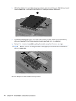
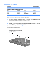
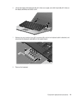
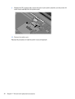
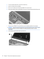
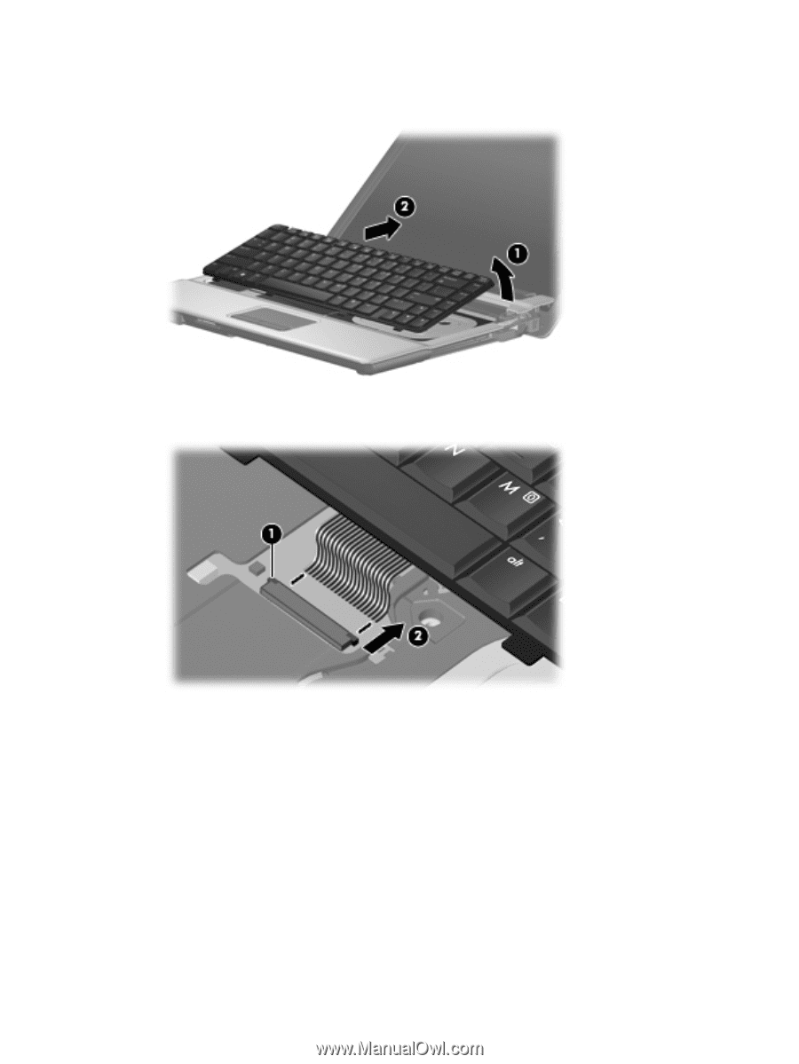
6. Lift the rear edge of the keyboard (1) until it rests at an angle, and slide it back (2) until it rests on the display assembly and switch cover. 7. Release the zero insertion force (ZIF) connector (1) to which the keyboard cable is attached, and disconnect the keyboard cable (2) from the system board. 8. Remove the keyboard. Component replacement procedures 49
-
 1
1 -
2
-
3
-
4
-
5
-
6
-
7
-
8
-
9
-
10
-
11
-
12
-
13
-
14
-
15
-
16
-
17
-
18
-
19
-
20
-
21
-
22
-
23
-
24
-
25
-
26
-
27
-
28
-
29
-
30
-
31
-
32
-
33
-
34
-
35
-
36
-
37
-
38
-
39
-
40
-
41
-
42
-
43
-
44
-
45
-
46
-
47
-
48
-
49
-
50
-
51
-
52
-
53
-
 54
54 -
 55
55 -
 56
56 -
 57
57 -
 58
58 -
 59
59 -
 60
60 -
 61
61 -
 62
62 -
 63
63 -
 64
64 -
65
-
66
-
67
-
68
-
69
-
70
-
71
-
72
-
73
-
74
-
75
-
76
-
77
-
78
-
79
-
80
-
81
-
82
-
83
-
84
-
85
-
86
-
87
-
88
-
89
-
90
-
91
-
92
-
93
-
94
-
95
-
96
-
97
-
98
-
99
-
100
-
101
-
102
-
103
-
104
-
105
-
106
-
107
-
108
-
109
-
110
-
111
-
112
-
113
-
114
-
115
-
116
-
117
-
118
-
119
-
120
-
121
-
122
-
123
-
124
-
125
-
126
-
127
-
128
-
129
-
130
-
131
-
132
-
133
-
134
-
135
-
136
-
137
-
138
-
139
-
140
-
141
-
142
-
143
-
144
-
145
-
146
-
147
-
148
-
149
-
150
 |
 |
6.
Lift the rear edge of the keyboard
(1)
until it rests at an angle, and slide it back
(2)
until it rests on
the display assembly and switch cover.
7.
Release the zero insertion force (ZIF) connector
(1)
to which the keyboard cable is attached, and
disconnect the keyboard cable
(2)
from the system board.
8.
Remove the keyboard.
Component replacement procedures
49