HP 540 HP 540 Notebook PC and HP 541 Notebook PC - Maintenance and Service Gui - Page 76
System board
 |
View all HP 540 manuals
Add to My Manuals
Save this manual to your list of manuals |
Page 76 highlights
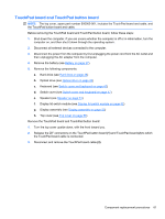
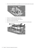
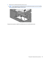
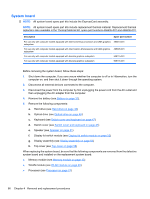
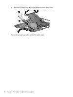
System board NOTE: All system board spare part kits include the ExpressCard assembly. NOTE: All system board spare part kits include replacement thermal material. Replacement thermal material is also available in the Thermal Material Kit, spare part numbers 456605-001 and 456606-001. Description Spare part number For use only with computer models equipped with Intel Core2 Duo processors and UMA graphics 495410-001 subsystem For use only with computer models equipped with Intel Celeron M processors and UMA graphics 495395-001 subsystem For use only with computer models equipped with discrete graphics subsystem 509115-001 For use only with computer models equipped with discrete graphics subsystem 509116-001 Before removing the system board, follow these steps: 1. Shut down the computer. If you are unsure whether the computer is off or in Hibernation, turn the computer on, and then shut it down through the operating system. 2. Disconnect all external devices connected to the computer. 3. Disconnect the power from the computer by first unplugging the power cord from the AC outlet and then unplugging the AC adapter from the computer. 4. Remove the battery (see Battery on page 37). 5. Remove the following components: a. Hard drive (see Hard drive on page 38) b. Optical drive (see Optical drive on page 45) c. Keyboard (see Switch cover and keyboard on page 47) d. Switch cover (see Switch cover and keyboard on page 47) e. Speaker (see Speaker on page 51) f. Display lid switch module (see Display lid switch module on page 52) g. Display assembly (see Display assembly on page 53) h. Top cover (see Top cover on page 58) When replacing the system board, be sure that the following components are removed from the defective system board and installed on the replacement system board: ● Memory module (see Memory module on page 43) ● WLAN module (see WLAN module on page 40) ● Processor (see Processor on page 74) 66 Chapter 4 Removal and replacement procedures
-
 1
1 -
2
-
3
-
4
-
5
-
6
-
7
-
8
-
9
-
10
-
11
-
12
-
13
-
14
-
15
-
16
-
17
-
18
-
19
-
20
-
21
-
22
-
23
-
24
-
25
-
26
-
27
-
28
-
29
-
30
-
31
-
32
-
33
-
34
-
35
-
36
-
37
-
38
-
39
-
40
-
41
-
42
-
43
-
44
-
45
-
46
-
47
-
48
-
49
-
50
-
51
-
52
-
53
-
54
-
55
-
56
-
57
-
58
-
59
-
60
-
61
-
62
-
63
-
64
-
65
-
66
-
67
-
68
-
69
-
70
-
 71
71 -
 72
72 -
 73
73 -
 74
74 -
 75
75 -
 76
76 -
 77
77 -
 78
78 -
 79
79 -
 80
80 -
 81
81 -
82
-
83
-
84
-
85
-
86
-
87
-
88
-
89
-
90
-
91
-
92
-
93
-
94
-
95
-
96
-
97
-
98
-
99
-
100
-
101
-
102
-
103
-
104
-
105
-
106
-
107
-
108
-
109
-
110
-
111
-
112
-
113
-
114
-
115
-
116
-
117
-
118
-
119
-
120
-
121
-
122
-
123
-
124
-
125
-
126
-
127
-
128
-
129
-
130
-
131
-
132
-
133
-
134
-
135
-
136
-
137
-
138
-
139
-
140
-
141
-
142
-
143
-
144
-
145
-
146
-
147
-
148
-
149
-
150
 |
 |