HP 540 HP 540 Notebook PC and HP 541 Notebook PC - Maintenance and Service Gui - Page 77
until the external monitor connector, Flex the left side of the base enclosure
 |
View all HP 540 manuals
Add to My Manuals
Save this manual to your list of manuals |
Page 77 highlights
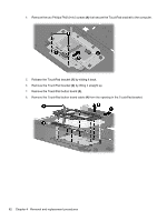
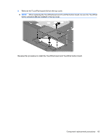
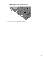
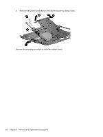
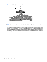
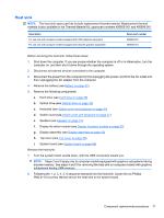
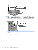
Remove the system board: 1. Remove the RJ-11 jack (1) from the clip built into the base enclosure and remove the RJ-11 jack cable from the hook (2) built into the base enclosure. 2. Disconnect the fan cable (3) and the Bluetooth module cable (4) from the system board. 3. Remove the two Phillips PM2.0×6.0 screws (1) and the Torx T8M2.5×4.0 screw (2) that secure the system board to the base enclosure. 4. Flex the left side of the base enclosure (1) until the external monitor connector (2) is clear of the opening in the base enclosure. 5. Lift the rear edge of the system board (3) until it rests at an angle. Component replacement procedures 67
-
 1
1 -
2
-
3
-
4
-
5
-
6
-
7
-
8
-
9
-
10
-
11
-
12
-
13
-
14
-
15
-
16
-
17
-
18
-
19
-
20
-
21
-
22
-
23
-
24
-
25
-
26
-
27
-
28
-
29
-
30
-
31
-
32
-
33
-
34
-
35
-
36
-
37
-
38
-
39
-
40
-
41
-
42
-
43
-
44
-
45
-
46
-
47
-
48
-
49
-
50
-
51
-
52
-
53
-
54
-
55
-
56
-
57
-
58
-
59
-
60
-
61
-
62
-
63
-
64
-
65
-
66
-
67
-
68
-
69
-
70
-
71
-
 72
72 -
 73
73 -
 74
74 -
 75
75 -
 76
76 -
 77
77 -
 78
78 -
 79
79 -
 80
80 -
 81
81 -
 82
82 -
83
-
84
-
85
-
86
-
87
-
88
-
89
-
90
-
91
-
92
-
93
-
94
-
95
-
96
-
97
-
98
-
99
-
100
-
101
-
102
-
103
-
104
-
105
-
106
-
107
-
108
-
109
-
110
-
111
-
112
-
113
-
114
-
115
-
116
-
117
-
118
-
119
-
120
-
121
-
122
-
123
-
124
-
125
-
126
-
127
-
128
-
129
-
130
-
131
-
132
-
133
-
134
-
135
-
136
-
137
-
138
-
139
-
140
-
141
-
142
-
143
-
144
-
145
-
146
-
147
-
148
-
149
-
150
 |
 |
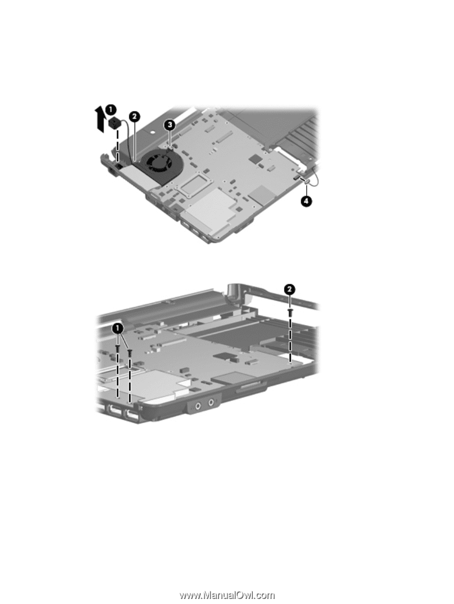
Remove the system board:
1.
Remove the RJ-11 jack
(1)
from the clip built into the base enclosure and remove the RJ-11 jack
cable from the hook
(2)
built into the base enclosure.
2.
Disconnect the fan cable
(3)
and the Bluetooth module cable
(4)
from the system board.
3.
Remove the two Phillips PM2.0×6.0 screws
(1)
and the Torx T8M2.5×4.0 screw
(2)
that secure the
system board to the base enclosure.
4.
Flex the left side of the base enclosure
(1)
until the external monitor connector
(2)
is clear of the
opening in the base enclosure.
5.
Lift the rear edge of the system board
(3)
until it rests at an angle.
Component replacement procedures
67