HP 540 HP 540 Notebook PC and HP 541 Notebook PC - Maintenance and Service Gui - Page 58
it rests on the display assembly., Lift the switch cover
 |
View all HP 540 manuals
Add to My Manuals
Save this manual to your list of manuals |
Page 58 highlights
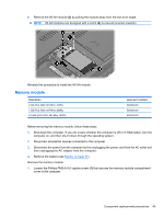
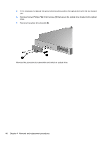
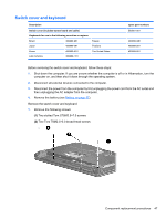
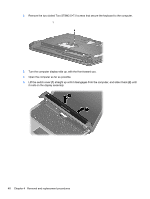
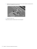
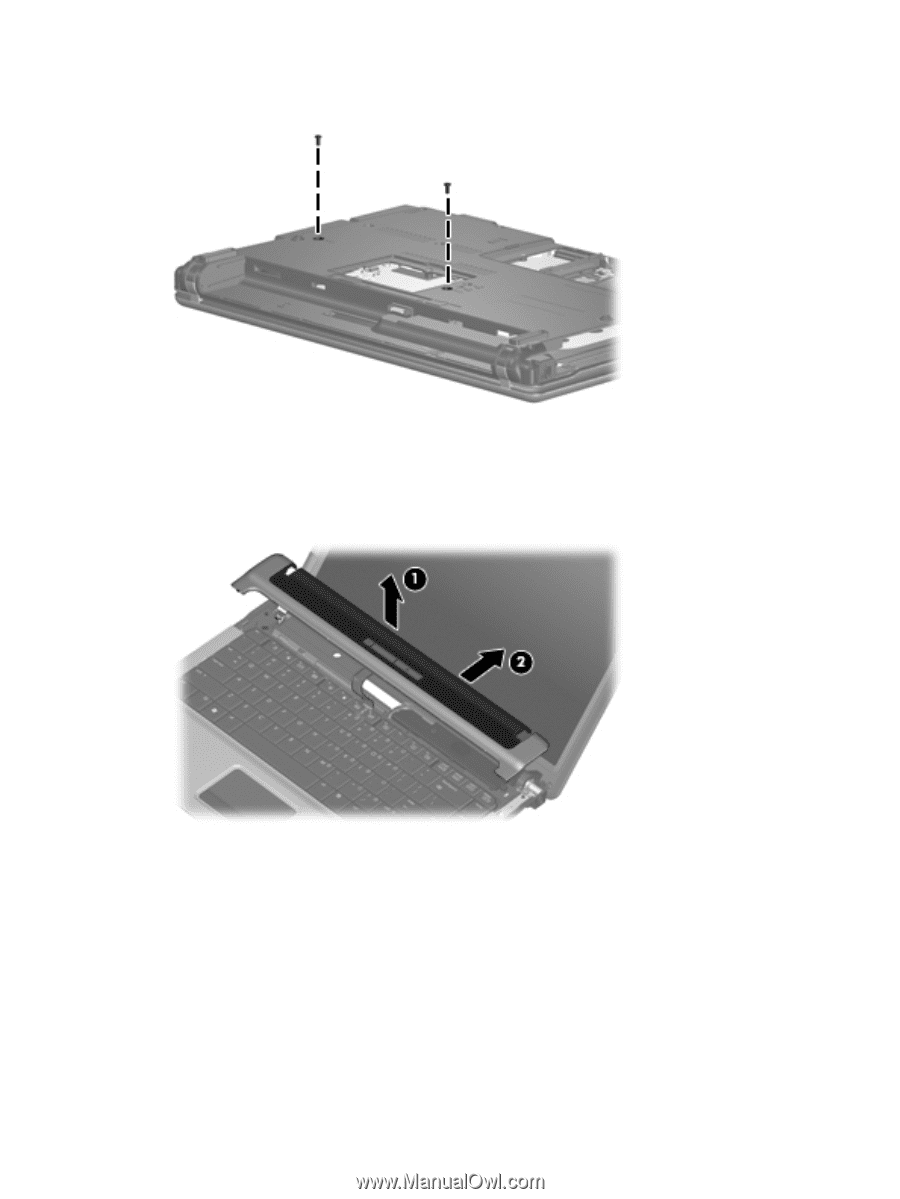
2. Remove the two slotted Torx ST8M2.5×7.0 screws that secure the keyboard to the computer. 3. Turn the computer display-side up, with the front toward you. 4. Open the computer as far as possible. 5. Lift the switch cover (1) straight up until it disengages from the computer, and slide it back (2) until it rests on the display assembly. 48 Chapter 4 Removal and replacement procedures
-
 1
1 -
2
-
3
-
4
-
5
-
6
-
7
-
8
-
9
-
10
-
11
-
12
-
13
-
14
-
15
-
16
-
17
-
18
-
19
-
20
-
21
-
22
-
23
-
24
-
25
-
26
-
27
-
28
-
29
-
30
-
31
-
32
-
33
-
34
-
35
-
36
-
37
-
38
-
39
-
40
-
41
-
42
-
43
-
44
-
45
-
46
-
47
-
48
-
49
-
50
-
51
-
52
-
 53
53 -
 54
54 -
 55
55 -
 56
56 -
 57
57 -
 58
58 -
 59
59 -
 60
60 -
 61
61 -
 62
62 -
 63
63 -
64
-
65
-
66
-
67
-
68
-
69
-
70
-
71
-
72
-
73
-
74
-
75
-
76
-
77
-
78
-
79
-
80
-
81
-
82
-
83
-
84
-
85
-
86
-
87
-
88
-
89
-
90
-
91
-
92
-
93
-
94
-
95
-
96
-
97
-
98
-
99
-
100
-
101
-
102
-
103
-
104
-
105
-
106
-
107
-
108
-
109
-
110
-
111
-
112
-
113
-
114
-
115
-
116
-
117
-
118
-
119
-
120
-
121
-
122
-
123
-
124
-
125
-
126
-
127
-
128
-
129
-
130
-
131
-
132
-
133
-
134
-
135
-
136
-
137
-
138
-
139
-
140
-
141
-
142
-
143
-
144
-
145
-
146
-
147
-
148
-
149
-
150
 |
 |
2.
Remove the two slotted Torx ST8M2.5×7.0 screws that secure the keyboard to the computer.
3.
Turn the computer display-side up, with the front toward you.
4.
Open the computer as far as possible.
5.
Lift the switch cover
(1)
straight up until it disengages from the computer, and slide it back
(2)
until
it rests on the display assembly.
48
Chapter 4
Removal and replacement procedures