HP 6005 Hardware Reference Guide - HP Compaq 6005 Pro Microtower Model - Page 42
CAUTION, Sliding a Hard Drive into the Drive Bay
 |
View all HP 6005 manuals
Add to My Manuals
Save this manual to your list of manuals |
Page 42 highlights
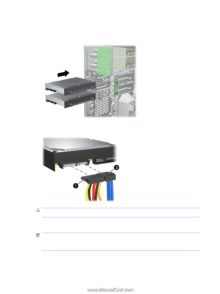
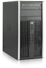
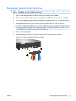
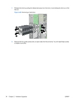
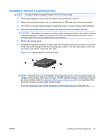
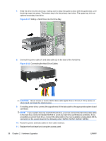
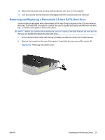
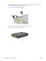
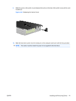
7. Slide the drive into the drive bay, making sure to align the guide screws with the guide slots, until the drive snaps into place. The bottom bay is for the primary hard drive. The upper bay is for an optional secondary hard drive. Figure 2-31 Sliding a Hard Drive into the Drive Bay 8. Connect the power cable (1) and data cable (2) to the back of the hard drive. Figure 2-32 Connecting the Hard Drive Cables CAUTION: Never crease or bend a SATA data cable tighter than a 30 mm (1.18 in) radius. A sharp bend can break the internal wires. 9. If installing a new drive, connect the opposite end of the data cable to the appropriate system board connector. NOTE: If your system has only one SATA hard drive, you must connect the hard drive data cable to the dark blue connector labeled SATA0 to avoid any hard drive performance problems. If you are adding a second hard drive, connect the data cable to the next available (unpopulated) SATA connector on the system board in the following order: SATA0, SATA1, SATA2, SATA3. 10. Route the power and data cables in their cable retainers. 11. Replace the front bezel and computer access panel. 36 Chapter 2 Hardware Upgrades ENWW
-
 1
1 -
2
-
3
-
4
-
5
-
6
-
7
-
8
-
9
-
10
-
11
-
12
-
13
-
14
-
15
-
16
-
17
-
18
-
19
-
20
-
21
-
22
-
23
-
24
-
25
-
26
-
27
-
28
-
29
-
30
-
31
-
32
-
33
-
34
-
35
-
36
-
 37
37 -
 38
38 -
 39
39 -
 40
40 -
 41
41 -
 42
42 -
 43
43 -
 44
44 -
 45
45 -
 46
46 -
 47
47 -
48
-
49
-
50
-
51
-
52
-
53
-
54
-
55
-
56
-
57
-
58
-
59
-
60
-
61
-
62
 |
 |