HP Cisco MDS 9120 Cisco MDS 9200 Series Hardware Installation Guide (OL-16188- - Page 100
Connecting to the COM1 Port
 |
View all HP Cisco MDS 9120 manuals
Add to My Manuals
Save this manual to your list of manuals |
Page 100 highlights
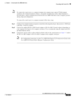
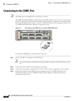
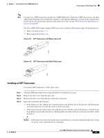
Connecting to the COM1 Port Chapter 3 Connecting the Cisco MDS 9200 Series Connecting to the COM1 Port Note The COM1 port is not supported for connection to a console. The COM1 port (labeled COM1) is an RS-232 port with a DB-9 interface. (See Figure 3-2.) You can use this port to connect to an external serial communication device such as a modem. For information about how to turn off hardware flow control, see the Cisco MDS 9000 Family CLI Configuration Guide or the Cisco MDS 9000 Family Fabric Manager Configuration Guide. Figure 3-2 Connecting to the COM1 Port on the Cisco MDS 9200 Series 1 FAN STATUS 2 FAN-MOD-2 MDS 9216i CONSOLE MGMT 10/100 COM1 STATUS 1 2 3 4 5 6 7 8 9 10 11 12 13 14 LINK- GE1 LINK- GE2 LINK- -SPEED LINK- -SPEED LINK- -SPEED 1 2 3 4 5 6 7 8 9 10 11 12 13 14 15 16 STATUS SYSTEM RESET 122005 To connect the COM1 port to a modem, follow these steps: Step 1 Connect the DB-9 serial adapter to the COM1 port. Note Connect the modem to the COM1 port using the adapters and cables provided with the accessory kit. Step 2 Step 3 Step 4 Connect the RJ-45 to DB-25 modem adapter to the modem. Connect these two adapters using the RJ-45 to RJ-45 rollover cable (or equivalent crossover cable). If the default settings for the COM1 port were modified, see the Cisco MDS 9000 Family CLI Configuration Guide or the Cisco MDS 9000 Family Fabric Manager Configuration Guide for information on this feature. Cisco MDS 9200 Series Hardware Installation Guide 3-4 OL-16188-01
-
 1
1 -
2
-
3
-
4
-
5
-
6
-
7
-
8
-
9
-
10
-
11
-
12
-
13
-
14
-
15
-
16
-
17
-
18
-
19
-
20
-
21
-
22
-
23
-
24
-
25
-
26
-
27
-
28
-
29
-
30
-
31
-
32
-
33
-
34
-
35
-
36
-
37
-
38
-
39
-
40
-
41
-
42
-
43
-
44
-
45
-
46
-
47
-
48
-
49
-
50
-
51
-
52
-
53
-
54
-
55
-
56
-
57
-
58
-
59
-
60
-
61
-
62
-
63
-
64
-
65
-
66
-
67
-
68
-
69
-
70
-
71
-
72
-
73
-
74
-
75
-
76
-
77
-
78
-
79
-
80
-
81
-
82
-
83
-
84
-
85
-
86
-
87
-
88
-
89
-
90
-
91
-
92
-
93
-
94
-
 95
95 -
 96
96 -
 97
97 -
 98
98 -
 99
99 -
 100
100 -
 101
101 -
 102
102 -
 103
103 -
 104
104 -
 105
105 -
106
-
107
-
108
-
109
-
110
-
111
-
112
-
113
-
114
-
115
-
116
-
117
-
118
-
119
-
120
-
121
-
122
-
123
-
124
-
125
-
126
-
127
-
128
-
129
-
130
-
131
-
132
-
133
-
134
-
135
-
136
-
137
-
138
-
139
-
140
-
141
-
142
-
143
-
144
-
145
-
146
-
147
-
148
-
149
-
150
-
151
-
152
-
153
-
154
-
155
-
156
-
157
-
158
-
159
-
160
-
161
-
162
-
163
-
164
 |
 |
