HP Cisco MDS 9120 Cisco MDS 9200 Series Hardware Installation Guide (OL-16188- - Page 137
Parameters, Symbol, Minimum, Typical, Units, Notes/Conditions, Table B-31
 |
View all HP Cisco MDS 9120 manuals
Add to My Manuals
Save this manual to your list of manuals |
Page 137 highlights
Appendix B Technical Specifications SFP Transceiver Specifications Table B-31 provides the optical specifications for the Cisco 2-Gbps CWDM SFP transceivers. Table B-31 Optical Specification for Cisco 2-Gbps CWDM SFP Transceivers Parameters Transmitter Center Wavelength Symbol Minimum Typical λc x-4 - Side-mode SMSR 30 - Suppression Ratio Transmitter Optical Pout 0.0 Output Power Receiver Optical Pin -28.0 - Input Power (BER
-
 1
1 -
2
-
3
-
4
-
5
-
6
-
7
-
8
-
9
-
10
-
11
-
12
-
13
-
14
-
15
-
16
-
17
-
18
-
19
-
20
-
21
-
22
-
23
-
24
-
25
-
26
-
27
-
28
-
29
-
30
-
31
-
32
-
33
-
34
-
35
-
36
-
37
-
38
-
39
-
40
-
41
-
42
-
43
-
44
-
45
-
46
-
47
-
48
-
49
-
50
-
51
-
52
-
53
-
54
-
55
-
56
-
57
-
58
-
59
-
60
-
61
-
62
-
63
-
64
-
65
-
66
-
67
-
68
-
69
-
70
-
71
-
72
-
73
-
74
-
75
-
76
-
77
-
78
-
79
-
80
-
81
-
82
-
83
-
84
-
85
-
86
-
87
-
88
-
89
-
90
-
91
-
92
-
93
-
94
-
95
-
96
-
97
-
98
-
99
-
100
-
101
-
102
-
103
-
104
-
105
-
106
-
107
-
108
-
109
-
110
-
111
-
112
-
113
-
114
-
115
-
116
-
117
-
118
-
119
-
120
-
121
-
122
-
123
-
124
-
125
-
126
-
127
-
128
-
129
-
130
-
131
-
 132
132 -
 133
133 -
 134
134 -
 135
135 -
 136
136 -
 137
137 -
 138
138 -
 139
139 -
 140
140 -
 141
141 -
 142
142 -
143
-
144
-
145
-
146
-
147
-
148
-
149
-
150
-
151
-
152
-
153
-
154
-
155
-
156
-
157
-
158
-
159
-
160
-
161
-
162
-
163
-
164
 |
 |

B-17
Cisco MDS 9200 Series Hardware Installation Guide
OL-16188-01
Appendix B
Technical Specifications
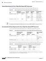
SFP Transceiver Specifications
Table B-31
provides the optical specifications for the Cisco 2-Gbps CWDM SFP transceivers.
Note
•
Parameters are specified over temperature and at end of life unless otherwise noted.
•
When shorter distances of single-mode fiber are used, it is necessary to insert an in-line optical
attenuator in the link to avoid overloading the receiver.
For information about safety, regulatory, and standards compliance, refer to the
Regulatory Compliance
and Safety Information for the Cisco MDS 9000 Family
.
Table B-31
Optical Specification for Cisco 2-Gbps CWDM SFP Transceivers
Parameters
Symbol
Minimum
Typical
Maximum
Units
Notes/Conditions
Transmitter Center
Wavelength
λ
c
x-4
–
x+7
nm
Available center
wavelengths are
1470, 1490,
1510, 1530,
1550, 1570,
1590, and 1610
nm
Side-mode
Suppression Ratio
SMSR
30
–
–
dB
–
Transmitter Optical
Output Power
P
out
0.0
5.0
dBm
Average power
coupled into
single-mode fiber
Receiver Optical
Input Power (BER
<10-12 with PRBS
2-7-1)
P
in
-28.0
–
-7.0
dBm
At 2.12 Gbps,
140°F (60°C)
case temperature
Receiver Optical
Input Power (BER
<10-12 with PRBS
2-7-1)
P
in
-29.0
–
-7.0
dBm
At 1.25 Gbps,
140°F (60°C)
case temperature
Receiver Optical
Input Wavelength
λ
in
1450
–
1620
nm
–
Transmitter
Extinction Ratio
OMI
9
–
–
dB
–
Dispersion Penalty at
62.1 miles (100 km)
–
–
–
3
dB
At 2.12 Gbps
Dispersion Penalty at
62.1 miles (100 km)
–
–
–
2
dB
At 1.25 Gbps