HP Cisco MDS 9120 Cisco MDS 9200 Series Hardware Installation Guide (OL-16188- - Page 92
Removing and Installing Power Supplies, Removing a Power Supply
 |
View all HP Cisco MDS 9120 manuals
Add to My Manuals
Save this manual to your list of manuals |
Page 92 highlights
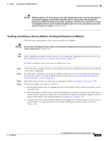
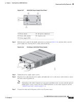
Removing and Installing Components Chapter 2 Installing the Cisco MDS 9200 Series Removing and Installing Power Supplies The Cisco MDS 9200 Series supports dual 845-W AC power supplies that monitor output voltage and provide status to the supervisor module. This section includes the following topics: • Removing a Power Supply, page 2-36 • Installing a Power Supply, page 2-36 A flat-blade or Phillips screwdriver is required to perform these procedures. Warning Voltage is present on the backplane when the system is operating. To reduce risk of an electric shock, keep hands and fingers out of the power supply bays and backplane areas. Statement 166 Warning Power supply captive installation screws must be tight to ensure protective grounding continuity. Statement 289 Note You can replace a faulty power supply while the system is operating provided the other power supply is functioning. Removing a Power Supply To remove a power supply, follow these steps: Step 1 Step 2 Step 3 Step 4 Step 5 Turn the power switch to the off (0) position. Loosen the screw on the power cable retainer and disconnect the power cable from the power supply being removed. Loosen the captive screw on the power supply. Grasp the power supply handle with one hand and slide it out of the chassis. Install a blank filler panel if the power supply bay is to remain empty. Installing a Power Supply To install a power supply, follow these steps: Step 1 Step 2 Step 3 Ensure that the system (earth) ground connection has been made. For ground connection instructions, see the "Installing the Switch in a Cabinet with Insufficient Front Clearance" section on page 2-11. If the power supply bay has a filler panel, loosen the screws holding the panel and remove the panel. Verify that the power switch is in the off (0) position on the power supply you are installing. See Figure 2-21 for the location of the power switch. 2-36 Cisco MDS 9200 Series Hardware Installation Guide OL-16188-01
-
 1
1 -
2
-
3
-
4
-
5
-
6
-
7
-
8
-
9
-
10
-
11
-
12
-
13
-
14
-
15
-
16
-
17
-
18
-
19
-
20
-
21
-
22
-
23
-
24
-
25
-
26
-
27
-
28
-
29
-
30
-
31
-
32
-
33
-
34
-
35
-
36
-
37
-
38
-
39
-
40
-
41
-
42
-
43
-
44
-
45
-
46
-
47
-
48
-
49
-
50
-
51
-
52
-
53
-
54
-
55
-
56
-
57
-
58
-
59
-
60
-
61
-
62
-
63
-
64
-
65
-
66
-
67
-
68
-
69
-
70
-
71
-
72
-
73
-
74
-
75
-
76
-
77
-
78
-
79
-
80
-
81
-
82
-
83
-
84
-
85
-
86
-
 87
87 -
 88
88 -
 89
89 -
 90
90 -
 91
91 -
 92
92 -
 93
93 -
 94
94 -
 95
95 -
 96
96 -
 97
97 -
98
-
99
-
100
-
101
-
102
-
103
-
104
-
105
-
106
-
107
-
108
-
109
-
110
-
111
-
112
-
113
-
114
-
115
-
116
-
117
-
118
-
119
-
120
-
121
-
122
-
123
-
124
-
125
-
126
-
127
-
128
-
129
-
130
-
131
-
132
-
133
-
134
-
135
-
136
-
137
-
138
-
139
-
140
-
141
-
142
-
143
-
144
-
145
-
146
-
147
-
148
-
149
-
150
-
151
-
152
-
153
-
154
-
155
-
156
-
157
-
158
-
159
-
160
-
161
-
162
-
163
-
164
 |
 |
