HP Cisco MDS 9120 Cisco MDS 9200 Series Hardware Installation Guide (OL-16188- - Page 81
Location of System Ground on the Cisco MDS 9200 Series
 |
View all HP Cisco MDS 9120 manuals
Add to My Manuals
Save this manual to your list of manuals |
Page 81 highlights
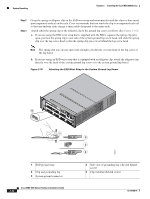
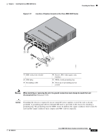
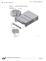
Chapter 2 Installing the Cisco MDS 9200 Series Grounding the Chassis Figure 2-17 Location of System Ground on the Cisco MDS 9200 Series 1 2 MDS 9216i 3 4 5 6 7 8 9 10 11 12 13 14 LINK GE1 LINK GE2 12 3 6 5 4 116899 1 ESD socket (on switch) 2 ESD plug 3 Grounding cable 4 Screws, M4, with square cone washers 5 NRTL listed grounding lug 6 Close-up of grounding pad on switch Warning When installing or replacing the unit, the ground connection must always be made first and disconnected last. Statement 1046 Caution Grounding the chassis is required if you are using DC power supplies, even if the rack is already grounded. A grounding pad with two threaded M4 holes is provided on the chassis for attaching a grounding lug. The ground lug must be NRTL listed. In addition the copper conductor (wires) must be used and the copper conductor must comply with NEC code for ampacity. OL-16188-01 Cisco MDS 9200 Series Hardware Installation Guide 2-25
-
 1
1 -
2
-
3
-
4
-
5
-
6
-
7
-
8
-
9
-
10
-
11
-
12
-
13
-
14
-
15
-
16
-
17
-
18
-
19
-
20
-
21
-
22
-
23
-
24
-
25
-
26
-
27
-
28
-
29
-
30
-
31
-
32
-
33
-
34
-
35
-
36
-
37
-
38
-
39
-
40
-
41
-
42
-
43
-
44
-
45
-
46
-
47
-
48
-
49
-
50
-
51
-
52
-
53
-
54
-
55
-
56
-
57
-
58
-
59
-
60
-
61
-
62
-
63
-
64
-
65
-
66
-
67
-
68
-
69
-
70
-
71
-
72
-
73
-
74
-
75
-
 76
76 -
 77
77 -
 78
78 -
 79
79 -
 80
80 -
 81
81 -
 82
82 -
 83
83 -
 84
84 -
 85
85 -
 86
86 -
87
-
88
-
89
-
90
-
91
-
92
-
93
-
94
-
95
-
96
-
97
-
98
-
99
-
100
-
101
-
102
-
103
-
104
-
105
-
106
-
107
-
108
-
109
-
110
-
111
-
112
-
113
-
114
-
115
-
116
-
117
-
118
-
119
-
120
-
121
-
122
-
123
-
124
-
125
-
126
-
127
-
128
-
129
-
130
-
131
-
132
-
133
-
134
-
135
-
136
-
137
-
138
-
139
-
140
-
141
-
142
-
143
-
144
-
145
-
146
-
147
-
148
-
149
-
150
-
151
-
152
-
153
-
154
-
155
-
156
-
157
-
158
-
159
-
160
-
161
-
162
-
163
-
164
 |
 |
