HP Dc5700 Hardware Reference Guide - dc5700 MT - Page 33
CAUTION, Connecting the Optical Drive Cables
 |
UPC - 882780819535
View all HP Dc5700 manuals
Add to My Manuals
Save this manual to your list of manuals |
Page 33 highlights
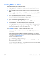
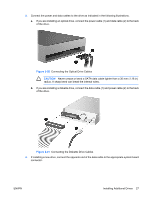
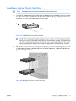
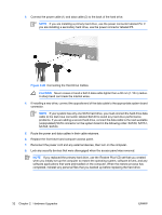
3. Connect the power and data cables to the drive as indicated in the following illustrations. a. If you are installing an optical drive, connect the power cable (1) and data cable (2) to the back of the drive. Figure 2-20 Connecting the Optical Drive Cables CAUTION Never crease or bend a SATA data cable tighter than a 30 mm (1.18 in) radius. A sharp bend can break the internal wires. b. If you are installing a diskette drive, connect the data cable (1) and power cable (2) to the back of the drive. Figure 2-21 Connecting the Diskette Drive Cables 4. If installing a new drive, connect the opposite end of the data cable to the appropriate system board connector. ENWW Installing Additional Drives 27
-
 1
1 -
2
-
3
-
4
-
5
-
6
-
7
-
8
-
9
-
10
-
11
-
12
-
13
-
14
-
15
-
16
-
17
-
18
-
19
-
20
-
21
-
22
-
23
-
24
-
25
-
26
-
27
-
 28
28 -
 29
29 -
 30
30 -
 31
31 -
 32
32 -
 33
33 -
 34
34 -
 35
35 -
 36
36 -
 37
37 -
 38
38 -
39
-
40
-
41
-
42
-
43
-
44
-
45
-
46
-
47
-
48
-
49
-
50
-
51
-
52
 |
 |
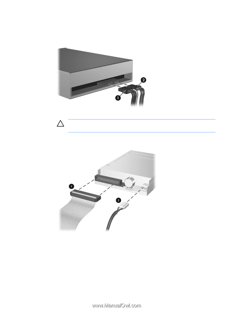
3.
Connect the power and data cables to the drive as indicated in the following illustrations.
a.
If you are installing an optical drive, connect the power cable (1) and data cable (2) to the back
of the drive.
Figure 2-20
Connecting the Optical Drive Cables
CAUTION
Never crease or bend a SATA data cable tighter than a 30 mm (1.18 in)
radius. A sharp bend can break the internal wires.
b.
If you are installing a diskette drive, connect the data cable (1) and power cable (2) to the back
of the drive.
Figure 2-21
Connecting the Diskette Drive Cables
4.
If installing a new drive, connect the opposite end of the data cable to the appropriate system board
connector.
ENWW
Installing Additional Drives
27