HP Dc5700 Hardware Reference Guide - dc5700 MT - Page 9
Rear Panel Components, Table 1-2 - graphics card
 |
UPC - 882780819535
View all HP Dc5700 manuals
Add to My Manuals
Save this manual to your list of manuals |
Page 9 highlights
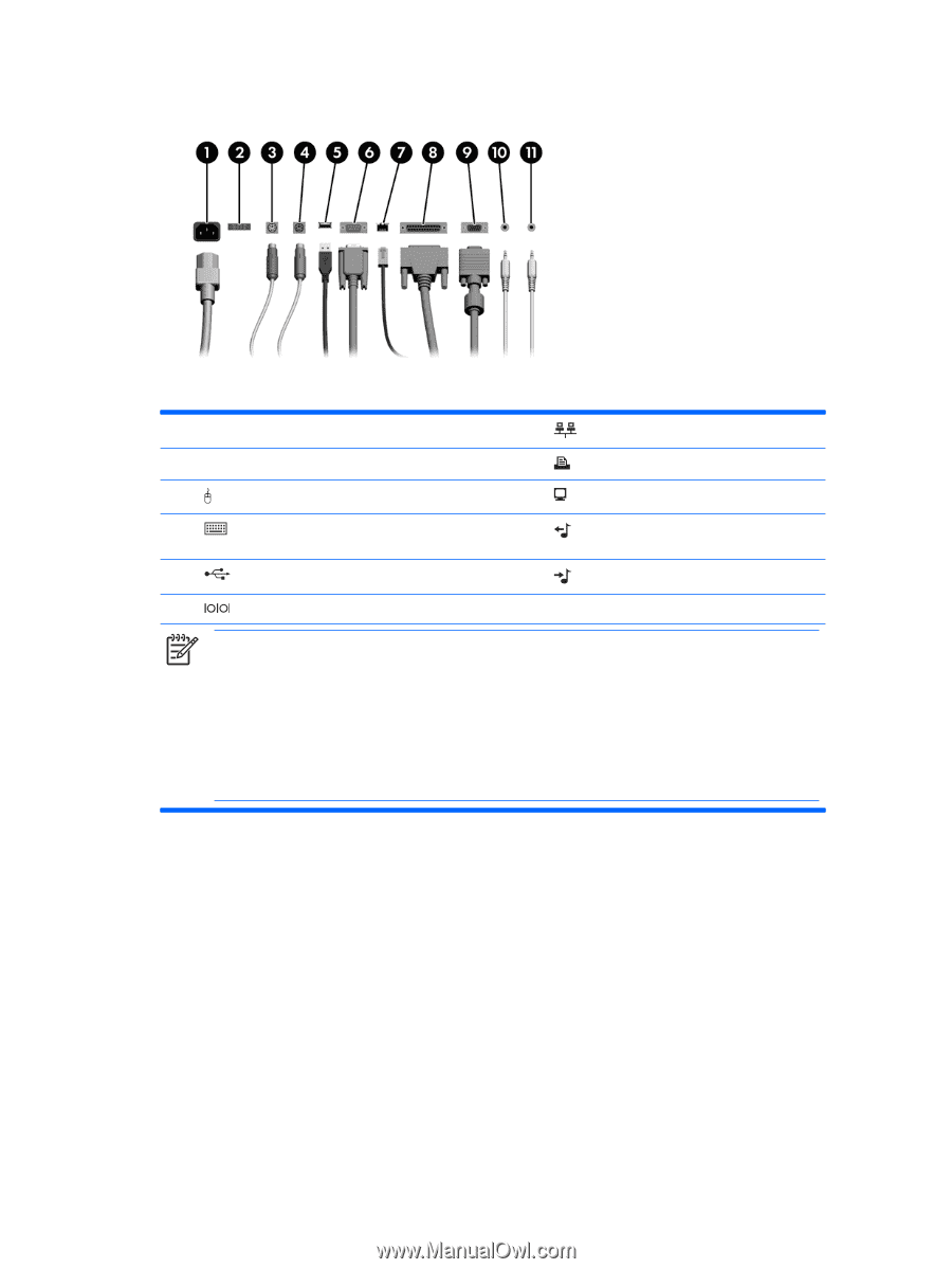
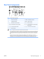
Rear Panel Components Table 1-2 Rear Panel Components 1 Power Cord Connector 2 Voltage Select Switch 3 PS/2 Mouse Connector (green) 4 PS/2 Keyboard Connector (purple) 5 Universal Serial Bus (USB) 6 Serial Connector 7 RJ-45 Network Connector 8 Parallel Connector 9 Monitor Connector 10 Line-Out Connector for powered audio devices (green) 11 Line-In Audio Connector (blue) NOTE Arrangement and number of connectors may vary by model. If a PCI graphics card is installed, the connectors on the card and the system board may be used at the same time. Some settings may need to be changed in Computer Setup to use both connectors. For information about Boot Order, refer to the Computer Setup (F10) Utility Guide on the Documentation and Diagnostics CD. The Line-In and Line-Out audio connectors can be "retasked" to work as either Line-In, Line-Out, or Microphone connectors by clicking the Realtek HD Audio Manager icon (a red speaker) in the task tray or the Realtek entry in the operating system's Control Panel and selecting the Retasking Enable option. ENWW Rear Panel Components 3
-
 1
1 -
2
-
3
-
 4
4 -
 5
5 -
 6
6 -
 7
7 -
 8
8 -
 9
9 -
 10
10 -
 11
11 -
 12
12 -
 13
13 -
 14
14 -
15
-
16
-
17
-
18
-
19
-
20
-
21
-
22
-
23
-
24
-
25
-
26
-
27
-
28
-
29
-
30
-
31
-
32
-
33
-
34
-
35
-
36
-
37
-
38
-
39
-
40
-
41
-
42
-
43
-
44
-
45
-
46
-
47
-
48
-
49
-
50
-
51
-
52
 |
 |