HP Dc7800 Hardware Reference Guide - HP Compaq dc7800 Convertible Minitower - Page 37
CAUTION, Connecting the Drive Cables Optical Drive shown
 |
UPC - 883585764365
View all HP Dc7800 manuals
Add to My Manuals
Save this manual to your list of manuals |
Page 37 highlights
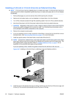
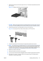
CAUTION: The bottom 5.25-inch drive bay has a shorter depth than the upper two bays. The bottom bay supports a half-height drive or other device that is no more than 14.5 cm (5.7 inches) in depth. Do not try to force a larger drive, such as an optical drive, into the bottom bay. This could cause damage to the drive and the system board. The use of unnecessary force when installing any drive into the drive bay may result in damage to the drive. NOTE: If you are installing a third optional drive, you may need to remove the strap that bundles the extra power connectors. 9. Connect the power cable (1) and data cable (2) to the rear of the optical drive or diskette drive. Figure 2-23 Connecting the Drive Cables (Optical Drive shown) 10. If you are installing a new drive, connect the opposite end of the data cable to the appropriate system board connector. NOTE: If you are installing a SATA optical drive, connect the first optical drive to the white SATA connector on the system board labeled SATA1. Connect a second optical drive to the orange SATA connector labeled SATA5. If you are installing a diskette drive, connect it to the connector on the system board labeled FLOPPY. If your are installing a media card reader, connect it to the USB system board connector labeled MEDIA CARD. 11. Replace the front bezel and computer access panel. 12. Reconnect the power cord and turn on the computer. 13. Lock any security devices that were disengaged when the computer access panel was removed. 14. Reconfigure the computer, if necessary. Refer to the Computer Setup (F10) Utility Guide for instructions on using Computer Setup. ENWW Installing Additional Drives 31
-
 1
1 -
2
-
3
-
4
-
5
-
6
-
7
-
8
-
9
-
10
-
11
-
12
-
13
-
14
-
15
-
16
-
17
-
18
-
19
-
20
-
21
-
22
-
23
-
24
-
25
-
26
-
27
-
28
-
29
-
30
-
31
-
 32
32 -
 33
33 -
 34
34 -
 35
35 -
 36
36 -
 37
37 -
 38
38 -
 39
39 -
 40
40 -
 41
41 -
 42
42 -
43
-
44
-
45
-
46
-
47
-
48
-
49
-
50
-
51
-
52
-
53
-
54
-
55
-
56
-
57
-
58
-
59
-
60
-
61
-
62
 |
 |
