HP Dv4 1540us Service Guide - Page 116
to lift the right side of the system board until it rests at an angle., Lift the system board
 |
UPC - 884962549049
View all HP Dv4 1540us manuals
Add to My Manuals
Save this manual to your list of manuals |
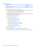
Page 116 highlights
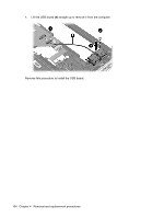
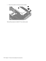
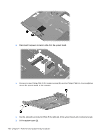
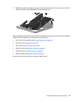
2. Disconnect the power connector cable from the system board. 3. Remove the two Phillips PM1.5×9.0 slotted screws (1), and the Phillips PM2.5×4.0 screw (2) that secure the system board to the computer. 4. Use the optical drive connector (1) to lift the right side of the system board until it rests at an angle. 5. Lift the system board (2). 108 Chapter 4 Removal and replacement procedures
-
 1
1 -
2
-
3
-
4
-
5
-
6
-
7
-
8
-
9
-
10
-
11
-
12
-
13
-
14
-
15
-
16
-
17
-
18
-
19
-
20
-
21
-
22
-
23
-
24
-
25
-
26
-
27
-
28
-
29
-
30
-
31
-
32
-
33
-
34
-
35
-
36
-
37
-
38
-
39
-
40
-
41
-
42
-
43
-
44
-
45
-
46
-
47
-
48
-
49
-
50
-
51
-
52
-
53
-
54
-
55
-
56
-
57
-
58
-
59
-
60
-
61
-
62
-
63
-
64
-
65
-
66
-
67
-
68
-
69
-
70
-
71
-
72
-
73
-
74
-
75
-
76
-
77
-
78
-
79
-
80
-
81
-
82
-
83
-
84
-
85
-
86
-
87
-
88
-
89
-
90
-
91
-
92
-
93
-
94
-
95
-
96
-
97
-
98
-
99
-
100
-
101
-
102
-
103
-
104
-
105
-
106
-
107
-
108
-
109
-
110
-
 111
111 -
 112
112 -
 113
113 -
 114
114 -
 115
115 -
 116
116 -
 117
117 -
 118
118 -
 119
119 -
 120
120 -
 121
121 -
122
-
123
-
124
-
125
-
126
-
127
-
128
-
129
-
130
-
131
-
132
-
133
-
134
-
135
-
136
-
137
-
138
-
139
-
140
-
141
-
142
-
143
-
144
-
145
-
146
-
147
-
148
-
149
-
150
-
151
-
152
-
153
-
154
-
155
-
156
-
157
-
158
-
159
-
160
-
161
-
162
-
163
-
164
-
165
-
166
-
167
-
168
-
169
-
170
-
171
-
172
-
173
-
174
-
175
-
176
-
177
-
178
-
179
-
180
-
181
-
182
-
183
-
184
-
185
-
186
-
187
-
188
-
189
-
190
-
191
-
192
-
193
-
194
-
195
-
196
 |
 |
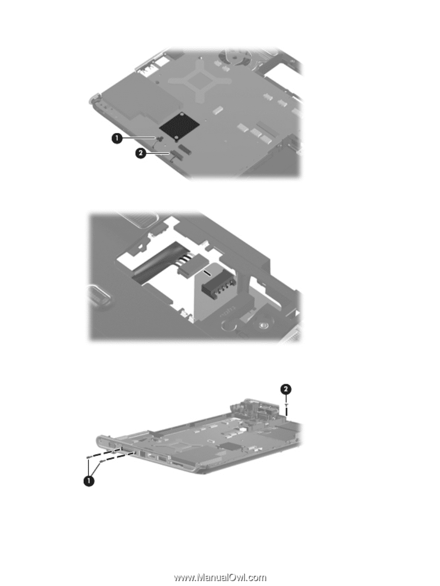
2.
Disconnect the power connector cable from the system board.
3.
Remove the two Phillips PM1.5×9.0 slotted screws
(1)
, and the Phillips PM2.5×4.0 screw
(2)
that
secure the system board to the computer.
4.
Use the optical drive connector
(1)
to lift the right side of the system board until it rests at an angle.
5.
Lift the system board
(2)
.
108
Chapter 4
Removal and replacement procedures