HP Dv4 1540us Service Guide - Page 98
If it is necessary to replace the wireless antenna assembly, remove the two Phillips PM2.5×4.0
 |
UPC - 884962549049
View all HP Dv4 1540us manuals
Add to My Manuals
Save this manual to your list of manuals |
Page 98 highlights
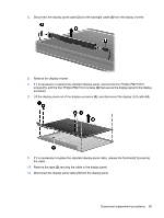
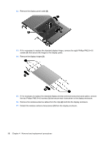
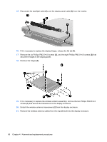
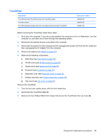
15. Disconnect the backlight cable (2), and the display panel cable (3) from the inverter. 16. If it is necessary to replace the display hinges, release the foil tab (1). 17. Remove the six Phillips PM2.5×4.0 screws (2), and the eight Phillips PM2.0×4.0 screws (3) that secure the hinges to the display panel. 18. Remove the hinges (4). 19. If it is necessary to replace the wireless antenna assembly, remove the two Phillips PM2.5×4.0 screws (1) that secure the transceivers to the display enclosure. 20. Detach the wireless antenna transceivers (2) from the display enclosure. 21. Remove the wireless antenna cables from the clips (3) built into the display enclosure. 90 Chapter 4 Removal and replacement procedures
-
 1
1 -
2
-
3
-
4
-
5
-
6
-
7
-
8
-
9
-
10
-
11
-
12
-
13
-
14
-
15
-
16
-
17
-
18
-
19
-
20
-
21
-
22
-
23
-
24
-
25
-
26
-
27
-
28
-
29
-
30
-
31
-
32
-
33
-
34
-
35
-
36
-
37
-
38
-
39
-
40
-
41
-
42
-
43
-
44
-
45
-
46
-
47
-
48
-
49
-
50
-
51
-
52
-
53
-
54
-
55
-
56
-
57
-
58
-
59
-
60
-
61
-
62
-
63
-
64
-
65
-
66
-
67
-
68
-
69
-
70
-
71
-
72
-
73
-
74
-
75
-
76
-
77
-
78
-
79
-
80
-
81
-
82
-
83
-
84
-
85
-
86
-
87
-
88
-
89
-
90
-
91
-
92
-
 93
93 -
 94
94 -
 95
95 -
 96
96 -
 97
97 -
 98
98 -
 99
99 -
 100
100 -
 101
101 -
 102
102 -
 103
103 -
104
-
105
-
106
-
107
-
108
-
109
-
110
-
111
-
112
-
113
-
114
-
115
-
116
-
117
-
118
-
119
-
120
-
121
-
122
-
123
-
124
-
125
-
126
-
127
-
128
-
129
-
130
-
131
-
132
-
133
-
134
-
135
-
136
-
137
-
138
-
139
-
140
-
141
-
142
-
143
-
144
-
145
-
146
-
147
-
148
-
149
-
150
-
151
-
152
-
153
-
154
-
155
-
156
-
157
-
158
-
159
-
160
-
161
-
162
-
163
-
164
-
165
-
166
-
167
-
168
-
169
-
170
-
171
-
172
-
173
-
174
-
175
-
176
-
177
-
178
-
179
-
180
-
181
-
182
-
183
-
184
-
185
-
186
-
187
-
188
-
189
-
190
-
191
-
192
-
193
-
194
-
195
-
196
 |
 |

15.
Disconnect the backlight cable
(2)
, and the display panel cable
(3)
from the inverter.
16.
If it is necessary to replace the display hinges, release the foil tab
(1)
.
17.
Remove the six Phillips PM2.5×4.0 screws
(2)
, and the eight Phillips PM2.0×4.0 screws
(3)
that
secure the hinges to the display panel.
18.
Remove the hinges
(4)
.
19.
If it is necessary to replace the wireless antenna assembly, remove the two Phillips PM2.5×4.0
screws
(1)
that secure the transceivers to the display enclosure.
20.
Detach the wireless antenna transceivers
(2)
from the display enclosure.
21.
Remove the wireless antenna cables from the clips
(3)
built into the display enclosure.
90
Chapter 4
Removal and replacement procedures