HP Dv4 1540us Service Guide - Page 117
WLAN module see, Memory modules see
 |
UPC - 884962549049
View all HP Dv4 1540us manuals
Add to My Manuals
Save this manual to your list of manuals |
Page 117 highlights
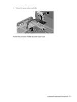
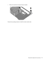
6. Release the system board (3) by sliding it to the right at an angle until the connectors on the left side of the system board disengage from the base enclosure. When replacing the system board, be sure that the following components are removed from the defective system board and installed on the replacement system board: ● Fan and heat sink assembly (see Fan and heat sink on page 114) ● Processor (see Processor on page 118) ● RTC battery (see RTC battery on page 69) ● Memory modules (see Memory module on page 67) ● WLAN module (see WLAN module on page 62) ● Modem module (see Modem module on page 99) Reverse the preceding procedure to install the system board. Component replacement procedures 109
-
 1
1 -
2
-
3
-
4
-
5
-
6
-
7
-
8
-
9
-
10
-
11
-
12
-
13
-
14
-
15
-
16
-
17
-
18
-
19
-
20
-
21
-
22
-
23
-
24
-
25
-
26
-
27
-
28
-
29
-
30
-
31
-
32
-
33
-
34
-
35
-
36
-
37
-
38
-
39
-
40
-
41
-
42
-
43
-
44
-
45
-
46
-
47
-
48
-
49
-
50
-
51
-
52
-
53
-
54
-
55
-
56
-
57
-
58
-
59
-
60
-
61
-
62
-
63
-
64
-
65
-
66
-
67
-
68
-
69
-
70
-
71
-
72
-
73
-
74
-
75
-
76
-
77
-
78
-
79
-
80
-
81
-
82
-
83
-
84
-
85
-
86
-
87
-
88
-
89
-
90
-
91
-
92
-
93
-
94
-
95
-
96
-
97
-
98
-
99
-
100
-
101
-
102
-
103
-
104
-
105
-
106
-
107
-
108
-
109
-
110
-
111
-
 112
112 -
 113
113 -
 114
114 -
 115
115 -
 116
116 -
 117
117 -
 118
118 -
 119
119 -
 120
120 -
 121
121 -
 122
122 -
123
-
124
-
125
-
126
-
127
-
128
-
129
-
130
-
131
-
132
-
133
-
134
-
135
-
136
-
137
-
138
-
139
-
140
-
141
-
142
-
143
-
144
-
145
-
146
-
147
-
148
-
149
-
150
-
151
-
152
-
153
-
154
-
155
-
156
-
157
-
158
-
159
-
160
-
161
-
162
-
163
-
164
-
165
-
166
-
167
-
168
-
169
-
170
-
171
-
172
-
173
-
174
-
175
-
176
-
177
-
178
-
179
-
180
-
181
-
182
-
183
-
184
-
185
-
186
-
187
-
188
-
189
-
190
-
191
-
192
-
193
-
194
-
195
-
196
 |
 |

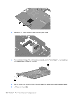
6.
Release the system board
(3)
by sliding it to the right at an angle until the connectors on the left
side of the system board disengage from the base enclosure.
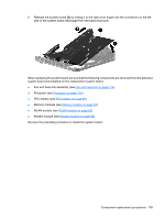
When replacing the system board, be sure that the following components are removed from the defective
system board and installed on the replacement system board:
●
Fan and heat sink assembly (see
Fan and heat sink
on page
114
)
●
Processor (see
Processor
on page
118
)
●
RTC battery (see
RTC battery
on page
69
)
●
Memory modules (see
Memory module
on page
67
)
●
WLAN module (see
WLAN module
on page
62
)
●
Modem module (see
Modem module
on page
99
)
Reverse the preceding procedure to install the system board.
Component replacement procedures
109