HP Dv4 1540us Service Guide - Page 90
CAUTION, The display assembly will be unsupported when the following screws are removed.
 |
UPC - 884962549049
View all HP Dv4 1540us manuals
Add to My Manuals
Save this manual to your list of manuals |
Page 90 highlights
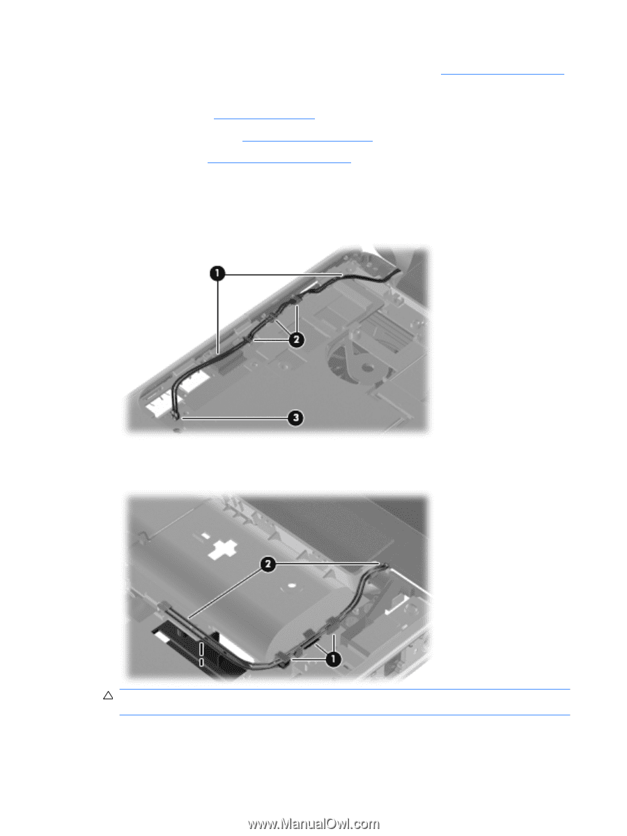
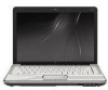
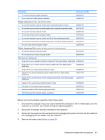
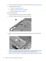
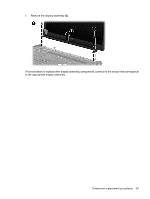
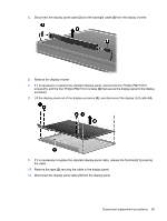
5. Disconnect the wireless antenna cables from the WLAN module (see WLAN module on page 62). 6. Remove the following components: a. Keyboard (see Keyboard on page 72) b. Keyboard cover (see Keyboard cover on page 74) c. Speaker (see Speaker assembly on page 77) Remove the display assembly: 1. Locate the wireless antenna cable (1), and remove from path (2). 2. Disconnect the wireless antenna cable from the system board (3). 3. Remove the wireless antenna cable from the path (1) and disconnect it from the system board (2). CAUTION: The display assembly will be unsupported when the following screws are removed. To prevent damage to the display assembly, support it before removing the screws. 4. Remove the four Phillips PM2.5×7.0 screws (1) that secure the display assembly to the computer. 82 Chapter 4 Removal and replacement procedures
-
 1
1 -
2
-
3
-
4
-
5
-
6
-
7
-
8
-
9
-
10
-
11
-
12
-
13
-
14
-
15
-
16
-
17
-
18
-
19
-
20
-
21
-
22
-
23
-
24
-
25
-
26
-
27
-
28
-
29
-
30
-
31
-
32
-
33
-
34
-
35
-
36
-
37
-
38
-
39
-
40
-
41
-
42
-
43
-
44
-
45
-
46
-
47
-
48
-
49
-
50
-
51
-
52
-
53
-
54
-
55
-
56
-
57
-
58
-
59
-
60
-
61
-
62
-
63
-
64
-
65
-
66
-
67
-
68
-
69
-
70
-
71
-
72
-
73
-
74
-
75
-
76
-
77
-
78
-
79
-
80
-
81
-
82
-
83
-
84
-
 85
85 -
 86
86 -
 87
87 -
 88
88 -
 89
89 -
 90
90 -
 91
91 -
 92
92 -
 93
93 -
 94
94 -
 95
95 -
96
-
97
-
98
-
99
-
100
-
101
-
102
-
103
-
104
-
105
-
106
-
107
-
108
-
109
-
110
-
111
-
112
-
113
-
114
-
115
-
116
-
117
-
118
-
119
-
120
-
121
-
122
-
123
-
124
-
125
-
126
-
127
-
128
-
129
-
130
-
131
-
132
-
133
-
134
-
135
-
136
-
137
-
138
-
139
-
140
-
141
-
142
-
143
-
144
-
145
-
146
-
147
-
148
-
149
-
150
-
151
-
152
-
153
-
154
-
155
-
156
-
157
-
158
-
159
-
160
-
161
-
162
-
163
-
164
-
165
-
166
-
167
-
168
-
169
-
170
-
171
-
172
-
173
-
174
-
175
-
176
-
177
-
178
-
179
-
180
-
181
-
182
-
183
-
184
-
185
-
186
-
187
-
188
-
189
-
190
-
191
-
192
-
193
-
194
-
195
-
196
 |
 |