HP Dv71270us Service Guide - Page 101
Remove the system board, Use the optical drive connector
 |
UPC - 884420712770
View all HP Dv71270us manuals
Add to My Manuals
Save this manual to your list of manuals |
Page 101 highlights
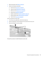
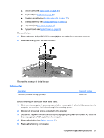
Remove the system board: 1. Disconnect the following cables: (1) USB board cable (2) Audio/infrared board cable (3) Modem module cable (4) Fan cable (5) Subwoofer cable 2. Remove the four Phillips PM2.5×4.0 screws that secure the system board to the base enclosure. 3. Use the optical drive connector (1) to lift the system board (2) until it rests at an angle. 4. Disconnect the power connector cable (3) from the system board. Component replacement procedures 93
-
 1
1 -
2
-
3
-
4
-
5
-
6
-
7
-
8
-
9
-
10
-
11
-
12
-
13
-
14
-
15
-
16
-
17
-
18
-
19
-
20
-
21
-
22
-
23
-
24
-
25
-
26
-
27
-
28
-
29
-
30
-
31
-
32
-
33
-
34
-
35
-
36
-
37
-
38
-
39
-
40
-
41
-
42
-
43
-
44
-
45
-
46
-
47
-
48
-
49
-
50
-
51
-
52
-
53
-
54
-
55
-
56
-
57
-
58
-
59
-
60
-
61
-
62
-
63
-
64
-
65
-
66
-
67
-
68
-
69
-
70
-
71
-
72
-
73
-
74
-
75
-
76
-
77
-
78
-
79
-
80
-
81
-
82
-
83
-
84
-
85
-
86
-
87
-
88
-
89
-
90
-
91
-
92
-
93
-
94
-
95
-
 96
96 -
 97
97 -
 98
98 -
 99
99 -
 100
100 -
 101
101 -
 102
102 -
 103
103 -
 104
104 -
 105
105 -
 106
106 -
107
-
108
-
109
-
110
-
111
-
112
-
113
-
114
-
115
-
116
-
117
-
118
-
119
-
120
-
121
-
122
-
123
-
124
-
125
-
126
-
127
-
128
-
129
-
130
-
131
-
132
-
133
-
134
-
135
-
136
-
137
-
138
-
139
-
140
-
141
-
142
-
143
-
144
-
145
-
146
-
147
-
148
-
149
-
150
-
151
-
152
-
153
-
154
-
155
-
156
-
157
-
158
-
159
-
160
-
161
-
162
-
163
-
164
-
165
-
166
-
167
-
168
-
169
-
170
-
171
-
172
-
173
-
174
-
175
-
176
-
177
-
178
-
179
-
180
-
181
 |
 |

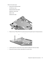
Remove the system board:
1.
Disconnect the following cables:
(1)
USB board cable
(2)
Audio/infrared board cable
(3)
Modem module cable
(4)
Fan cable
(5)
Subwoofer cable
2.
Remove the four Phillips PM2.5×4.0 screws that secure the system board to the base enclosure.
3.
Use the optical drive connector
(1)
to lift the system board
(2)
until it rests at an angle.
4.
Disconnect the power connector cable
(3)
from the system board.
Component replacement procedures
93