HP Dv71270us Service Guide - Page 110
Heat sink
 |
UPC - 884420712770
View all HP Dv71270us manuals
Add to My Manuals
Save this manual to your list of manuals |
Page 110 highlights
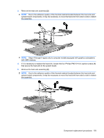
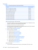
Heat sink NOTE: All heat sink spare kits include replacement thermal material. Description Spare part number For use only with computer models equipped with AMD processors and graphics subsystems with 488879-001 discrete memory For use only with computer models equipped with AMD processors and graphics subsystems with 490503-001 UMA memory For use only with computer models equipped with Intel processors and graphics subsystems with 480472-001 and 512-MB of discrete memory 481144-001 For use only with computer models equipped with Intel processors and graphics subsystems with 480473-001 256-MB of discrete memory Before removing the heat sink, follow these steps: 1. Shut down the computer. If you are unsure whether the computer is off or in Hibernation, turn the computer on, and then shut it down through the operating system. 2. Disconnect all external devices connected to the computer. 3. Disconnect the power from the computer by first unplugging the power cord from the AC outlet and then unplugging the AC adapter from the computer. 4. Remove the battery (see Battery on page 51). 5. Remove the following components: a. Hard drive (see Hard drive on page 56) b. Optical drive (see Optical drive on page 54) c. Switch cover (see Switch cover on page 66) d. Keyboard (see Keyboard on page 68) e. Speaker assembly (see Speaker assembly on page 72) f. Display assembly (see Display assembly on page 73) g. Top cover (see Top cover on page 82) h. System board (see System board on page 91) Remove the heat assembly: NOTE: Steps 1 through 3 apply only to computer models equipped with graphics subsystems with discrete memory. See steps 4 through 6 for heat sink removal instructions for computer models equipped with graphics subsystems with UMA memory. 1. Turn the system board upside down, with the expansion port 3 and external monitor port toward you. 2. Loosen the seven Phillips PM2.0×10.0 captive screws (1) that secure the heat sink assembly to the system board. 102 Chapter 4 Removal and replacement procedures
-
 1
1 -
2
-
3
-
4
-
5
-
6
-
7
-
8
-
9
-
10
-
11
-
12
-
13
-
14
-
15
-
16
-
17
-
18
-
19
-
20
-
21
-
22
-
23
-
24
-
25
-
26
-
27
-
28
-
29
-
30
-
31
-
32
-
33
-
34
-
35
-
36
-
37
-
38
-
39
-
40
-
41
-
42
-
43
-
44
-
45
-
46
-
47
-
48
-
49
-
50
-
51
-
52
-
53
-
54
-
55
-
56
-
57
-
58
-
59
-
60
-
61
-
62
-
63
-
64
-
65
-
66
-
67
-
68
-
69
-
70
-
71
-
72
-
73
-
74
-
75
-
76
-
77
-
78
-
79
-
80
-
81
-
82
-
83
-
84
-
85
-
86
-
87
-
88
-
89
-
90
-
91
-
92
-
93
-
94
-
95
-
96
-
97
-
98
-
99
-
100
-
101
-
102
-
103
-
104
-
 105
105 -
 106
106 -
 107
107 -
 108
108 -
 109
109 -
 110
110 -
 111
111 -
 112
112 -
 113
113 -
 114
114 -
 115
115 -
116
-
117
-
118
-
119
-
120
-
121
-
122
-
123
-
124
-
125
-
126
-
127
-
128
-
129
-
130
-
131
-
132
-
133
-
134
-
135
-
136
-
137
-
138
-
139
-
140
-
141
-
142
-
143
-
144
-
145
-
146
-
147
-
148
-
149
-
150
-
151
-
152
-
153
-
154
-
155
-
156
-
157
-
158
-
159
-
160
-
161
-
162
-
163
-
164
-
165
-
166
-
167
-
168
-
169
-
170
-
171
-
172
-
173
-
174
-
175
-
176
-
177
-
178
-
179
-
180
-
181
 |
 |